The "Weeble", wobbles into being.

Home Model Engine Machinist Forum

Help Support Home Model Engine Machinist Forum:

This site may earn a commission from merchant affiliate links, including eBay, Amazon, and others.

Captain Jerry

Project of the Month Winner!!!
Project of the Month Winner
Joined
Dec 2, 2008
Messages
971
Reaction score
8


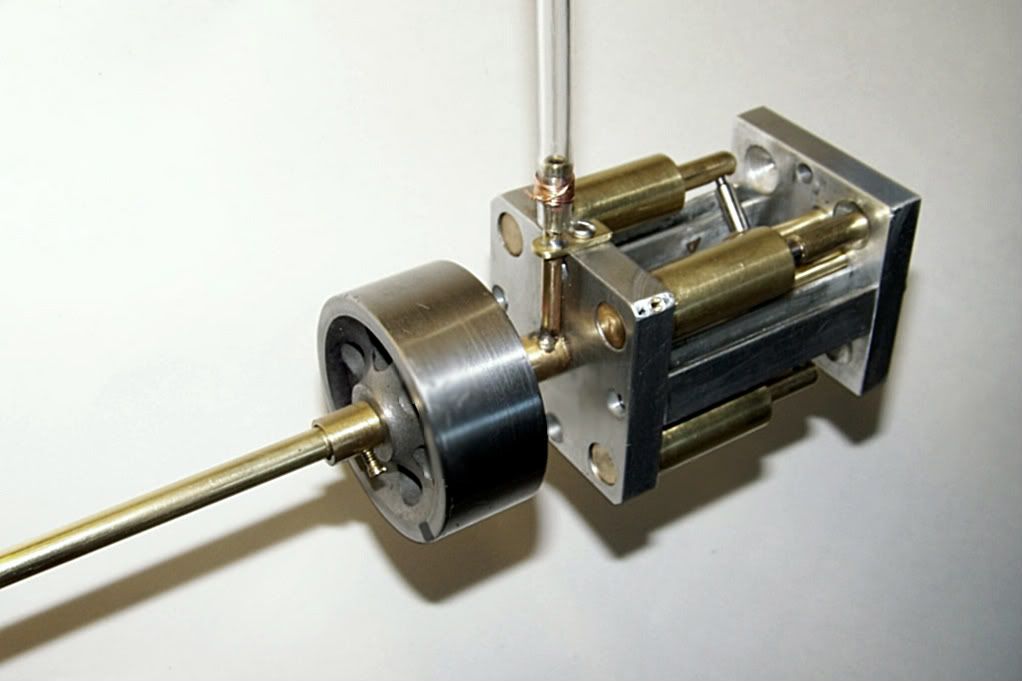
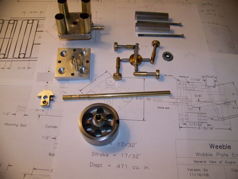
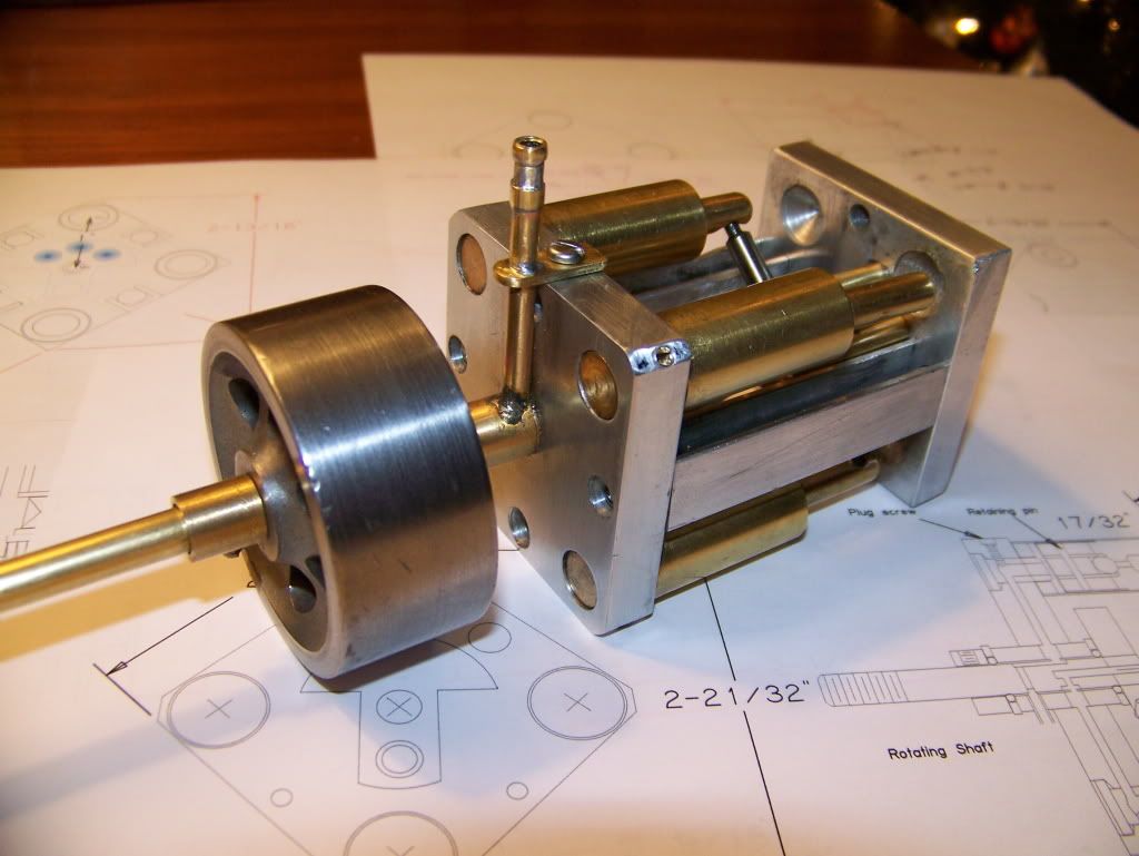
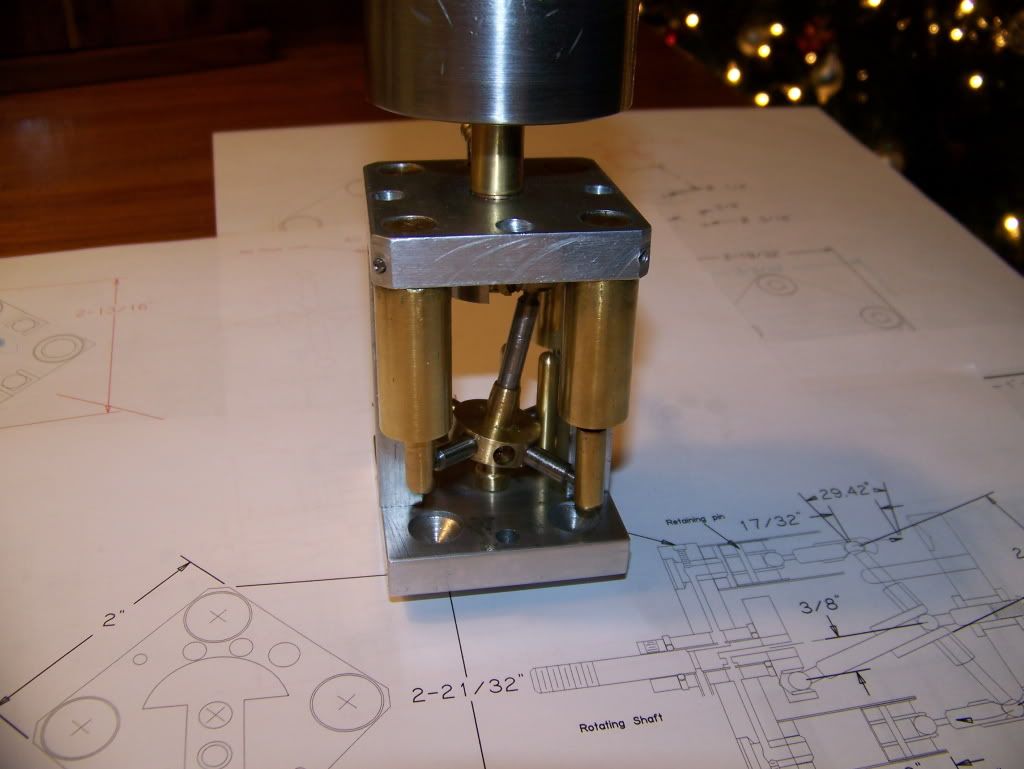
Here is a new engine that I am working on. It is almost complete but since there are mods that I will add, I'll call it a work in progress. This is a four cylinder, wobble plate engine of my own design but leans heavily on all previous designs for this type of engine. There are some innovations that I have not seen elsewhere but that doesn't mean that it hasn't been done before. This engine is more of a demonstration of principle than anything.

I don't have the skills or equipment to produce accurate scale models of historic engines so I just build little machines. One of the things that I wanted to achieve was a clean and uncluttered appearance so routing the air passages through the head plate was critical. I didn't want a lot of copper tubes with visible solder joints to distract from the simplicity of the design.

I am drawn to this type of engine due to the simple but slightly exotic mechanism. They belong to a class of engines called axial engines or barrel engines and they are similar but quite different from swash plate engines. They offer some challenges but are easily within the reach of an beginner. For the concepts involved and for some historic predecessors here is a link to check out.

http://www.dself.dsl.pipex.com/MUSEUM/POWER/unusualICeng/axial-ICeng/axial-IC.htm#smb


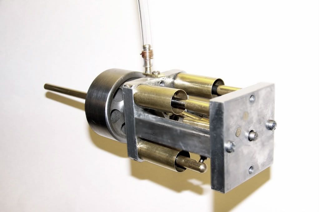
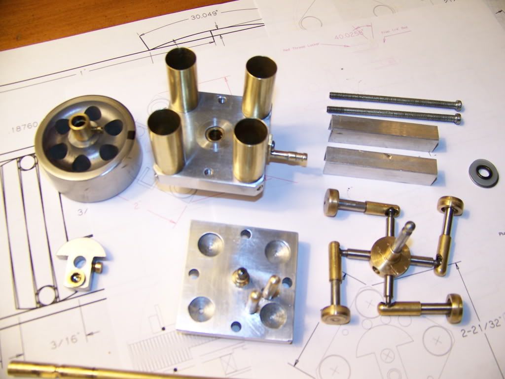
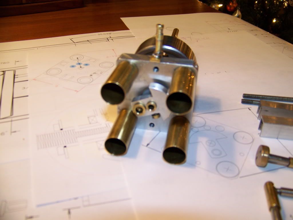
here are some pics of the parts before final assembly:

WeebleParts003.jpg


WeebleParts005.jpg


WeebleParts006.jpg


WeebleParts007.jpg


WeebleParts001.jpg


WeebleParts002.jpg


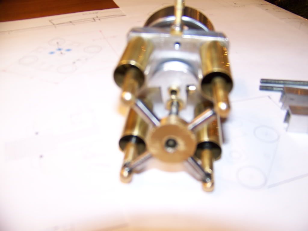
The engine is assembled and ready for testing but its too late in the evening to run the compressor so if I get some shop time tomorrow we will give it a go and I'll shoot some video.

Regards to all

Jerry
 
Jerry :bow: :bow:

Definitely a different looking engine. I will be watching for the video when you get it running tomorrow later today. Good luck with getting it tuned in on start up.

Cheers :)

Don
 
Its looking great Jerry and I too like the unique nature of the mechanism. Looking forward to the video!!

Well done!!!

Bill
 
I like it. Tell us more about the construction and particularly the innovations you made.
 
Hi Y'all

I have the Weeble ready to run but before I do I feel the need to preach to the choir. The many comments on Phil's excellent build of the twin mill engine tells me that we all hear the same question. After trying to answer it in a manner that will satisfy the questioner so many times, I have changed my approach.

When asked " What's it gonna do?", my answer is "It's already doing it." It's funny how many people seem to get it.

As a sailor, I am used to being looked at strangely. When friends ask me why I sail to the Bahamas every winter, when You can get a plane out of Miami and be there in 30 minutes, the answer is, "The trip is the destination." And when the question is "How many nights can you sit in the cockpit with a rum drink and just stare at the sky", my answer is "I don't know yet."

Back to engines.

I went to test the "Weeble" and realized that I hadn't gotten around to designing a base for it. I couldn't wait to see if it would run so I decided to go ahead without a base. Now that I have done that, the number of ideas that come up for the proper base is more than I want to deal with. Suggestions respectfully requested!!!

It runs!! It surprised me how easily it runs. A single rotary valve controls pressure and exhaust timing to all cylinders. There is no eccentric or cam to deal with. The only timing issue is the position of the web on the shaft. I decided to leave the shaft full round until I was satisfied with performance before milling a flat for the set screw. I set it up by eye for the test and locked the set screw in position on the round. When I find the optimum setting, I will mill a flat. I will also mill a flat 180 degrees from that location so that the rotation can be easily changed fro CW to CCW.

The engine is presently assembled with no o-rings on the piston. Better piston sealing is a future improvement. I squirted a liberal dose of oil into each of the cylinders and gave the shaft a couple of turns to distribute the oil and opened the air valve. I ran. With four cylinders, it runs very smoothly. I reduced the air pressure and it slowed, I opened the throttle and it revved smoothly. I reduced speed to a minimum and it came to a stop with a stop at about 20 PSI with a hiss of escaping air. I little manual help and it would make a few revs and come to a stop at the same position. Inspection showed air and oil escaping at the cylinder/head plate junction on one of the cylinders. I little tightening on the cylinder and now it runs at lower speeds, but as you can see in the video it begins to run a little rough. There could be lots of reasons for this but I suspect that the piston fit in one of the cylinders is a little sloppy. For now I'm going just going to run it and see how it does with a few hours.

I wanted to get the vids up tonight since my shop time is going to be curtailed for the next few weeks. Lights to hang, shopping to do, family coming. I'll check in when I can but I probably wont get much time to fiddle with it.

"Weeble wobbles but it don't fall down."

Weeblefronthigh.jpg


Weeblepicsandvid006.jpg


Merry Christmas to all
Jerry


Nice work, Jerry! Nice looking engine and a good runner!

Chuck
 
Jerry,
Congratulations on a runner!

That has an interesting motion. Kinda looks like a grasshopper trying to run away :)


Kevin
 
Jerry

Very nice engine. It's different but that's why it is so nice. Glad that you shared it with us. :bow: :bow: :bow:

Cheers :)

Don
 
CJ,

That's marvelous and such an unusual yet balanced motion.
icon_super.gif
icon_super.gif
.

Congratulations, I could watch it for hours.
mgyes.gif
mgeye-popping.gif


Best Regards
Bob

 
Captain Jerry said:
When asked " What's it gonna do?", my answer is "It's already doing it." It's funny how many people seem to get it.

when the question is "How many nights can you sit in the cockpit with a rum drink and just stare at the sky", my answer is "I don't know yet."

I often get asked are the engines I build going to do anything. All the engines I have made do something. For me it's not about what an engine will do after it's done. It's about what it's doing while im building all the parts.

The answer to "how many nights" for me would be "all of them".

Thats why I go to the names show and check in at websites like this, to hang out with and talk to the people who "get it"

Steve
 
Nice one Jerry, I really like that. Have you managed (or tried) to get it running on less than 20psi yet? I've made two rotary valve engines and neither will run at low (<10psi) pressure :(

(Looking at photo No 5 at the top of the thread I'm guessing that you dropped that flywheel at some point? My current project's cylinder has a similar floor-induced dent on the edge!)

Great work!
 
Looks Great Jerry!

Congrats on the runner!!!

Rick
 
Hats off to you Jerry for trying something different. Nice engine and it runs nicely. I get it!! ;D Enjoy it :bow: :bow: :bow:

Cheers,
Phil
 
I'm really tickled. ;D

It runs way better than I had hoped, without a lot of tinkering. After running it for about 30 minutes, when the oil was good and black, I disassembled it, washed it down with hotwater and detergent and put it back together and started it up again with fresh oil. It runs well down to about 15 PSI. When it stops tuning, there is some air leak but if I help it over the dead spot, it will make a full rev before coming to a stop. With four cylinders it should be able to tick over like a twin cylinder double acting mill engine with a power stroke every 90 degrees. Except for the short stroke. With 17/32 bore and 17/32 stroke, it is more of a high speed engine. Still, I would like it to run on less air. I would like it to run on my breath alone, but at my age, I don't like to build up that much internal pressure.

I can think of five reasons that it doesn't. Piston/cylinder clearance (loose), clearance (tight), cylinder/head leak (no gasket yet), friction or poor sealing at the valve or all of the above. Oiled paper head gaskets are the first and easiest adjustment. I don't want to use locktight on the cylinder mounting so that I can easily replace a cylinder.

Piston/cylinder clearance is a bit different on this engine. Then piston and rod are one piece, no wrist pin and the piston length is very short. It is only 1/4" long and with no o-ring, sealing is touchy.

Friction may come from a a too tight fit somewhere. There are 6 ball joints in this engine with 3/16dia. steel balls running in brass sockets. With no ball turning device, I produced them by filing to a template and testing with a tube gauge. These joints do not articulate at anywhere near the speed of a piston or shaft so run-in make take a little longer.

Rotary valves have a bad reputation, justly deserved. Air leaks around the shaft and can and will be addressed with adjustable packing glands at the shaft ends. The real problem is bleed over between the pressure and the exhaust ports on the rotary shaft. I have a design in mind and on paper but I don't think that I can execute it on a 1/4" valve shaft. If would require a 5/16" o-ring with a 1/32" thickness. I have not been able to find one like that. On a 3/8" shaft, a 1/16" o-ring might work but still seems to require a lathe or mill with CNC. Having neither, I am at a dead end. I am still thinking about it.

I have a v-4 with dual overhead rotary valves that would seem to solve the problem by having the pressure and exhaust valves in separate bores so there can be no bleed over. It was about 50% complete last year when it got shelved. It is now third in line for attention now. That design is not possible on this engine. One shaft only.

If you are still interested I rotary valves, I may be able to get some drawings together that I have done.

For now, I am going to work on the other fixes. I expect improved performance.

As to the flywheel, I didn't drop it on the floor. That's where it lived it's former life. Until a few years ago, it was a hardworking and well respected caster providing support to an outfeed table from my tablesaw. When I retired, it was "downsized" along with a lot of other equipment and languished in a junkbox waiting for an opportunity to serve. I have cleaned it up to serviceable condition but it is way hard and I had difficulty cutting it.

Thanks to all for the kind comments. Complements from this knowledgeable and talented group is surprising and encouraging.

Jerry
 
Instead of an o-ring for sealing the rotary valve, maybe a couple of teflon or delrin piston rings?
 
I don't know which material would be best. One or the other might work out better. The problem is not the material, it is the position. If the valve is controlling both pressure air and exhaust through a single passage to the cylinder, then the ports are in the same plane, perpendicular to the center line of the shaft. The seal must provide a seal between these ports.

Here is a quick and dirty sketch of what I am thinking. Cutting the grove for the diagonal o-ring is beyond me.

If the drawing doesn't show up I'll repost.

Jerry

View attachment Rotary Valve Sealing.pdf
 
Hello Jerry, we haven't met yet. My name is Ralph and I'm damn well impressed with your latest creation :bow:

I must say it took me until the very, very closeup video to understand the full working principle, got it now ;)


I also sneaked a peak at another video on your photobucket page.... WOW!!!!! :eek: (the principle I have the effect is the wow ;) )


I haven't been round much lately so it is nice to see a very inovative barstock engine in the engineering. I'm off to look for more now ;D


Thank you for showing it in such great detail, I will look out for more of your work.


Ralph.


Very nice engine!

The diagonal o-ring would be a nice set-up with the dividing head geared to the lead screw.
I guess you would cut the helix through 180 degrees, add an idler gear to reverse the gear train(without losing position) then feed back the other way.

just thinking aloud,

Kevin.
 

Latest posts

Back
Top