The Upshur Vertical Single

Home Model Engine Machinist Forum

Help Support Home Model Engine Machinist Forum:

This site may earn a commission from merchant affiliate links, including eBay, Amazon, and others.

Mattkguns

Active Member
Joined
Sep 28, 2012
Messages
31
Reaction score
5
Hey all, ive got a work in progress going, at the moment its only in the computer, but within the next week or two i need to get to cutting!

Heres a picture of the engine in Inventor
enginepic.png


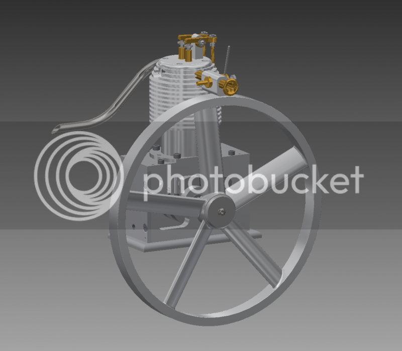
its been modified somewhat from the original plans, but primarily in style

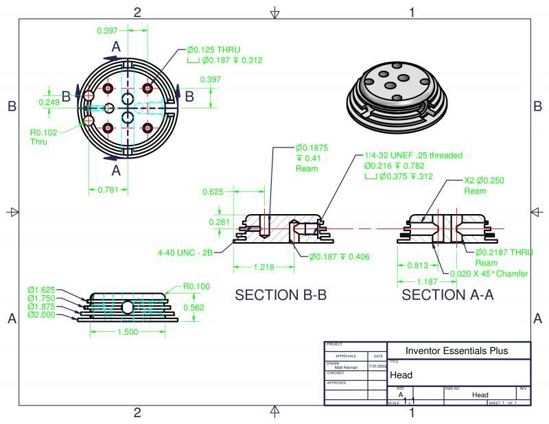
my starting question for you guys is about machining the head.
headdrawing.png

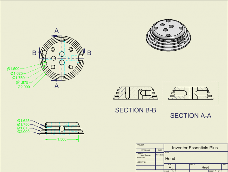
obviously the drawing isnt done here, but my question to you guys is how to go about doing the fins. my current plan is to stick a piece of 2" round in the vice on the mill and cut a square in the perimeter so that it can be flipped and held in the vice at 90s.
now heres where im not sure, should i drill all of the holes and features before i do the fins? or vice versa. my concern with the first method is the interrupted cutting may mess things up. But im thinking much less so than trying to drill and tap through the fins.

Thanks in advance,

ill try to keep this thread updated, though im painfully bad at keeping these things up to date.

Matt
 
Matt,
Is this based on the engine in Strictly IC ? If so I like the open crankcase and cylinder/head treatment. If you are going to build it as you have designed it, I would drill the holes first. You will have problems with the drill walking because of the fins as is. I don't know what you have for equipment, were you planing to turn the fins on the lathe? If you have a dividing head or rotary table I would suggest making a fixture to mount it to using the head bolts. Then you can move it around as needed.
Here's the link to my engine. http://www.homemodelenginemachinist.com/f31/my-first-engine-18599/
Art
 
Art, that looks to be the same engine. I got my plans from my professor at school. I'm doing a project class and he basically handed me the plans and said go. I didn't like a few design points, so I've modeled it in inventor and tweaked it.

The new head and cylinder design actually come from some of the pieces already having been made incorrectly, and to save on materials I edited the revisions in. The piston is a bit longer to account for the cylinder now being bolted onto the top plate.

My plan was to do everything but the bottom spark plug hole while still attached to the first piece of stock, part it, attach it to a small fixture (round piece of stock with holes) and drill the final hole and face it.
 
I would cut the fins first, then use an endmill rather than a drill to make the horizontal holes. The EM won't walk. The slots for the fins look to be about 1/16" wide, so I wouldn't want an interrupted cut there.
 
Mattkguns-

Could you please post the complete drawings? Bar-stock designs are great.


Frank
 
bronx, are you looking for the original packet of papers im working off of? or the set of drawings im working on?

kvom, im not sure about doing it all with an endmill, the sizes arent all standard for endmill.

heres a dimensioned drawing of it

Head21.jpg
 
The endmill is just to clear the depth of the fins (e.g., spotface). Once you get to "bedrock", you can then drill with the proper size for tapping. Your drawing shows a .375 opening for the 1/4-32 threaded hole(s)
 
ah, i think i see what youre getting at, just use the endmills to get past the fins.
i have to say, im still pretty nervous about the notion of plunging an endmill through those very thin fins.
 
Matt,
When I did mine I used a piece of round stock for the fixture mounted it in a three jaw chuck on the rotary table for all the side holes then mounted the chuck on the table to do the cooling fins. I've never had it overheat (melt the plastic carburetor yes) poor design of my intake manifold was at fault. Kvom is right as long as its solidly mounted and you don't go hog wild on feed rates it'll be fine. Though I would use a center cutting EM. One other thing don't lengthen the piston if anything cut out the sides like mine, it gets real bouncy, lively, fill in the blank. Instead I would shorten the height of the cylinder to compensate, been there done that. counter weight the crank as well.
Art
 
Last edited:
what if i were to lengthen the connecting rod instead of the piston? my trouble is that the cylinder is already made, with a cast iron (i think) liner inserted and seeing as i have until schools out in December to finish the motor, id prefer not to remake that piece.
 
Matt:

Could you post both the original, school plans, and the drawings for your modified version....if not too much trouble.

Thanks,


Frank
 
You have a choice between EM through fins or interrupted cut when making the fins. Try either on a piece of scrap and then decode which way works best. With the EM technique, you might also reinforce the fins with some shim stick between them.
 
Matt,
I don't see lengthening the rod being a problem unless there is a clearance problem with the Cylinder/crankcase. If you build the Hamilton Upshur designed carb just be aware that it is very temperamental. A sharper angle on the jet needle helps but you will have to adjust it for an idle or high speed. It does work well within those limitations though.
Art
 
i was planning to build the constant level bubble carburetor (Model Engine Builder issue #20), does that solve some of the issue, Art?

after some thinking ive realized it wouldnt, are there any good 2 needle designs that you guys like that arent a lot more complicated?
 
Matt,
I have never used a vapor carburetor, but since you have moved on from that idea that is a moot point anyways. I presently have a Perry rc carb on my engine, .177 diameter throat. I think it's still to much carb for the size of the engine, but it does run well with it. When at the names show a few years ago I bought the plans for the Jerry Howell two jet carb. I had problems picturing in my mind how the main body worked till I drew it up on Alibre. I haven't built the engine I planned to use it on so I never built the carb. At the show it was a mixed bag, several guys said it worked great, others not so well. Here's the website. http://www.model-engine-plans.com/engineplans/combustion/howell2jet.htm?31,28
It is quite reasonably priced so it may be worth looking at, maybe the intake can be scaled down so it runs better on a small engine, maybe someone else has a better idea.
 
Ive just had a small revelation.
My conglomeration of plans and notes include the article about the fuel tank i described, which is a vapor design. after re reading the notes (no help) and looking at the setup drawings (ah here we are) i realized that the upshur carb is in fact a liquid fuel carb, not a vapor setup.

woops

Some redesigning is in order, i suppose.

Im planning now to go ahead with building the upshur carb, and if it really runs rotten ill potentially look at an alternative.

Matt
 
So, i have a question for you guys

yall have read through a lot of plans at this point.

whats your favorite setup at this point.

one part per page?
or fit a few per page if they are related?

Matt
 
Back
Top