The Hubbard 1912

Home Model Engine Machinist Forum

Help Support Home Model Engine Machinist Forum:

This site may earn a commission from merchant affiliate links, including eBay, Amazon, and others.
@schilpr , I send you a privat message.

@Rac37 , nice job already. Do you have some tips for machining the parts??
 
hello Lawijt
i am looking for a new mill machine and the size of your
mill is the same as i would like to buy.
Please could you give me a link where did you buy it?
Thanks Kadora
 
Hi lawijt,
Grabbed a couple more pics. machining the main casting.
IMG_0127.jpg
After getting a few reference surfaces decided to drill exhaust port and hole tap , thread water inlet
IMG_0128.jpg
Re fixture in the sine vice to surface the angled areas on the side. Set for 20deg.
So far the aluminum main casting seems fine, no air pockets of any consequence. Once you get that 1st. reference surface and squared up vice
everything starts to follow. Oh by the way I did machine off the bottom sprue square to the rest of the casting. Gives another reference for squaring up with parallel in the vice.
In the next few days I plan to start on the liner again then figure out how I plan to bore out the casting for the liner.
How is the new mill coming along? Lookin forward to see your build start.

bob

IMG_0127.jpg


IMG_0128.jpg
 
hello lawijt,
Thought I would post a couple more pics.
#1 shows setup with coax indicator to find rough center for boring out for cylinder liner.
#2 Enlarging bore in action. Decided to use a 1/2" x 3" 2 flute end mill.
Running at 6900 rpm 6thou each pass. Normally use boring bar but thought
I would try cnc wizard. Turned out nice finish.
Next
I plan to start on cutting out the exhaust and transfer port on liner.
Oh well, till next time.
IMG_0129.jpg
IMG_0130.jpg
bob

IMG_0129.jpg


IMG_0130.jpg
 
Hi bob, you may call me Barry. Lawijt is just a forum name. hahaha.
My flywheel is done , but how did you make that exentric , that is new for me. The 2 bearing holders are also ready. Now I have to build the bearings from bronze.
But what they mean with the oil groove....I do not understand that very well.
I post later some pictures of what is done already.

Do you have some detailed pictures from the other pieces that you have build already? This is all new for me & I learn a lot from pictures.
 
Hi Barry,
Great to hear your making progress on the Hubbard.
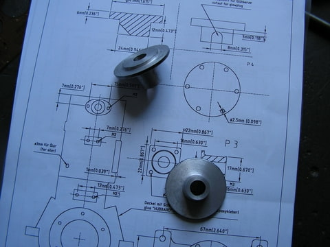
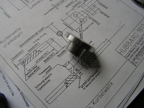
Normally I would have turned and drilled etc. the flywheel on the lathe.
Then re mount in 4 jaw chuck and after indicating exact center of the crank
shaft hole I would move carefully off center in one axis the required offset for the eccentric. However, since I used the mill for machining the flywheel I found it was real easy to re center and dial in the offset amount and "turn" the eccentric diameter. I've got to admit that after doing things manually before, cnc really makes certain jobs a whole lot simpler.
Don't get me wrong, I am new to cnc so a lot to learn. But having the various programing wizards available opens up a lot of new ways to machine.
Another method that I used one time involved the use of a rotary table.
Using on the mill I would find center and move over the required distance then setup that as my new center. Then just a matter of offsetting for the diameter of the eccentric.
Wow, I am getting long winded here hope I'am not confusing things too much.
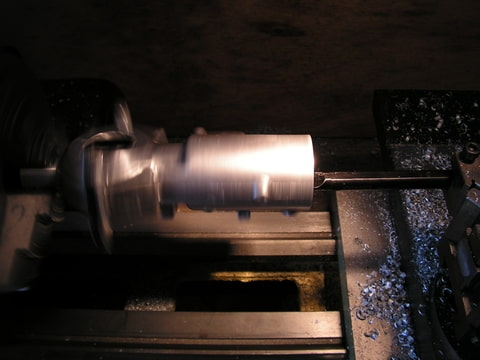
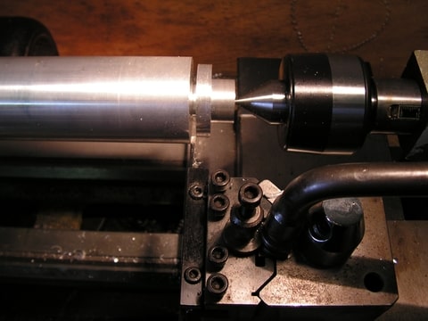
The oil grove allows for lubrication of the bearings and crank shaft. I had an old inside groove cutter that I used to "scratch" in a grove along the inside of the bearing maybe 1/2" or so while still in the lathe. Just locked the chuck and went in a few thou. at a time till I got a little groove for oil to make its way between bearing and shaft.
Hope this helps a little. Anxious to see some pics when you get a chance.
I'am sure there are many others here that can give us some more guidance as we progress.

take care,
Bob
 
Many years gao, I have built the Hubbart from Mr. Kornmüller. All worked well. Castings might have been a bit on the small side. I don't remember.
Getting it to run was a bit more work. Took several disassemblies to get the crankcase tight.


Nick
 
Do you still have that motor Nick? All tips & tricks are welcome. Also pictures offcourse.

Barry.
 
so far I'am wright now. Here some pictures:

Foto-8XDOT43Y.jpg


Foto-HXBTTSZR.jpg


Foto-QPOLLJ8T.jpg


Do somebody have a picture of the head? I don't understand the plan really good & also that oil groove in the bearing give me pain in my head.

Barry
 
Hello Barry,
Thanks for the pictures, looking good. I've not done much on mine will probably wait to turn the head after I get the liner finished and installed in the casting. Looks to be fairly straight forward 2 diameter turns and a notch out for the plug.
Come to think back I made one of my oil grooves using a pointed file and just filed a small groove about a 1/2" in on the bearing material. Hope that it will work out ok.
Sounds like its important to get a really good seals around the crankcase area.
Take care,
Bob
 
Hi Bob;

Can you make a picca from the bearings?
 
Hello Barry,
Not sure if these pictures will help. Showing one of my bearings with filing of the oil groove and using a groove cutter that I had on hand to cut inside bearing shaft. Just gradually cut away the groove a few thou. at a time.
At least the bronze material is pretty cut friendly.

Bob
IMG_0134.jpg
IMG_0135.jpg
IMG_0136.jpg

IMG_0134.jpg


IMG_0135.jpg


IMG_0136.jpg
 
I show the plans today to a friend...He told me directly that the drawnings are not complete. He is in my eyes a very good machinist. He build already 2 engines started from nothing. That is maybe why I don't understand it really good. With your pic Bob , I see what they mean.

Today I wake up & started at 7h00" & I stop at 12h00" with this....It is very urgent & will be need for a swimming pool. I did only sign some plans & started with the wiring. All the placement of the components , did I last week every evening:

Foto-FCLNM4NP.jpg


Than I visit very fast my mother. Bloodbags , oxygene , other bags , ect......I'am very sad right now. But the world turns around,so I hope the best.
In the afternoon my friend arrives & we put that 350kg of iron on place.

Foto-ICQHYDIQ.jpg


For the DRO we have not time. It will be installated after .....time. But I'am for the moment not in a hurry , so when I have a little time? I will be on the Lathe.
Some things right now have to be on the first place.
 
Barry,
Mill is looking nice, but more important hope all goes well with your mom.
You take care,

Bob
 
Hello Friends;

Saturday afternoon I have some time , so went to the Lathe.
Making the head for the Hubbard.

Here parting the workpiece off:

Foto-I3YJLFNY.jpg


Finished head. I takes a lot of hours to build it , but it fits great in the cilinder. And have to make it for the casting & not the measures from the plan.

Foto-DSMTZG4I.jpg


Do you make any progress Bob??

Barry
 
Hello Barry,
Your making nice progress, cylinder head look'in good.
I've not spent much time lately on the engine since pressing in the cylinder liner. Been helping buddy of mine get his sailboat rigged, launched and setup at new dock. Hope to get back working some on the Hubbard soon.
I will keep checking in to see how you are coming along which will give me ideas on how to finish on mine.
Take care,
Bob
IMG_0137.jpg

IMG_0138.jpg


IMG_0137.jpg
 

Latest posts

Back
Top