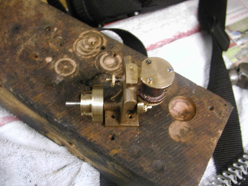
I've made progress over the last week or two, and it's really coming together.
The trunnion of course needs a nut to tension the spring.
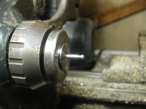
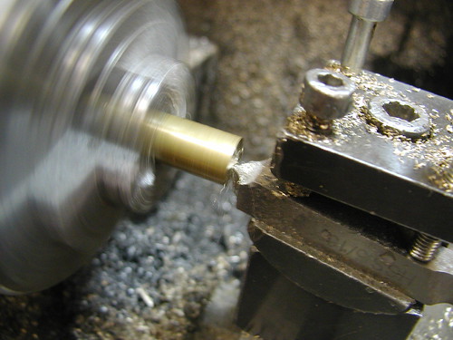
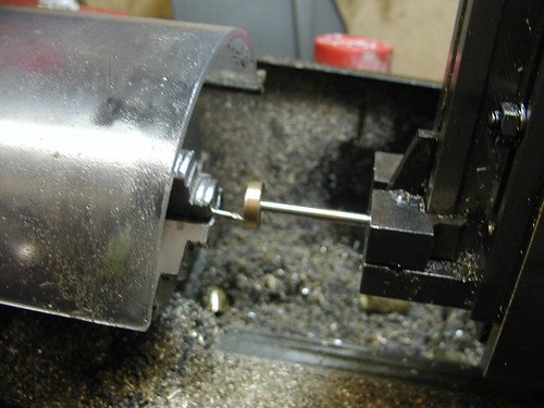
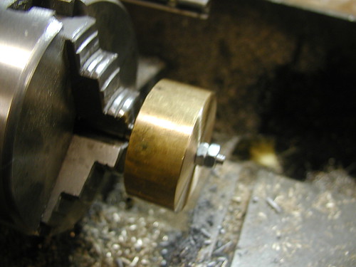
So I set up a piece of brass in the Hercus with the matching collet.
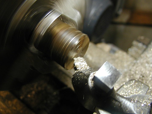
Facing the end of the stock.
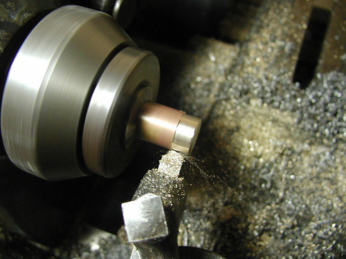
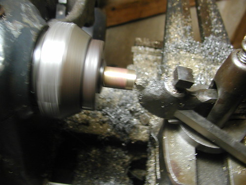
Turning to size.
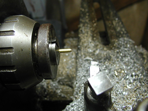
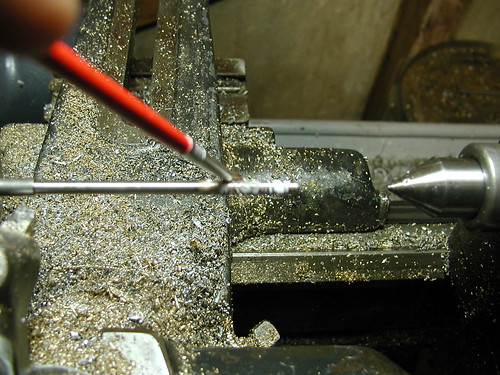
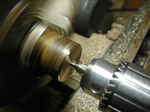
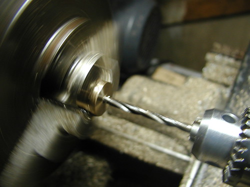
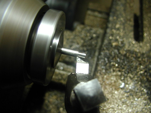
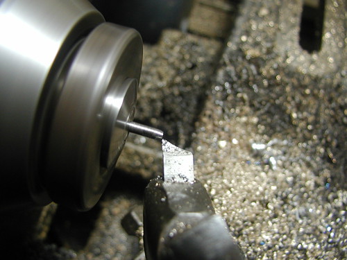
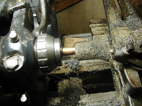
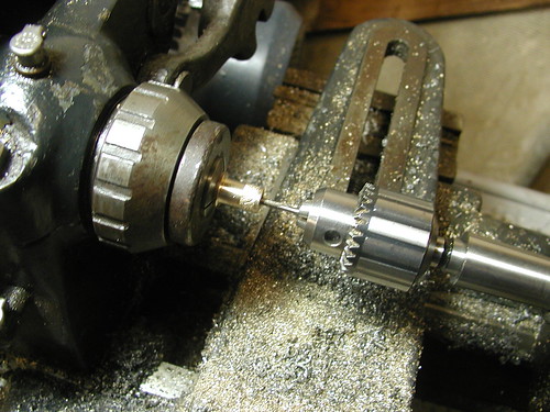
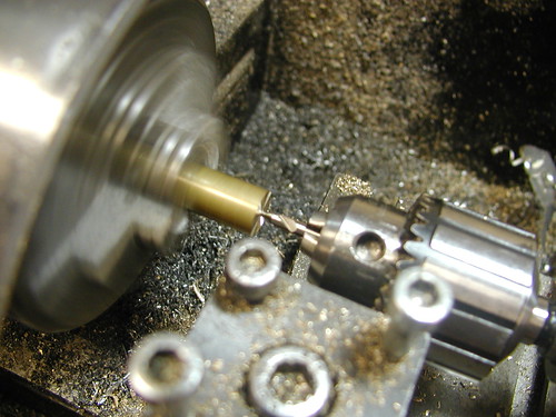
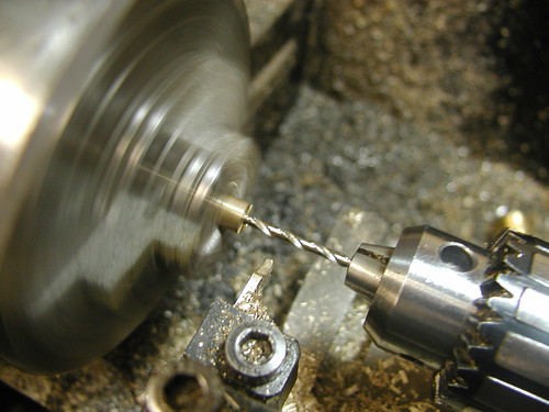
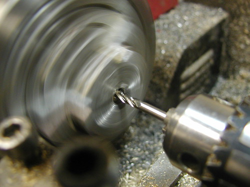
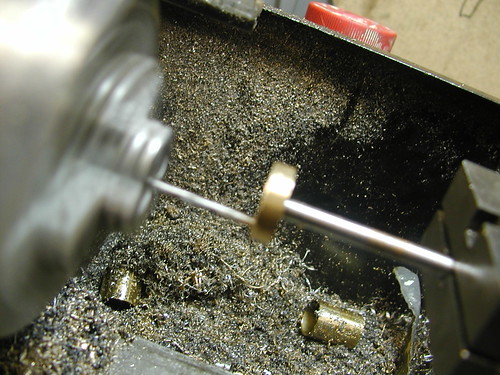
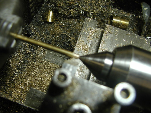
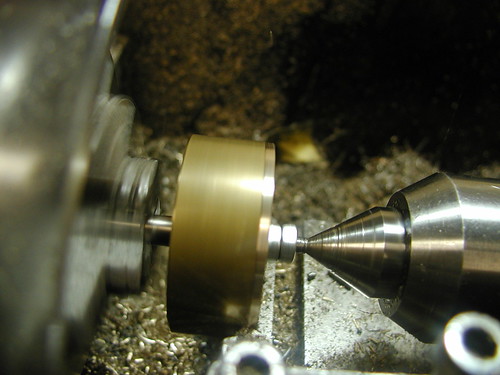
Centre drilling for the live centre.
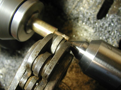
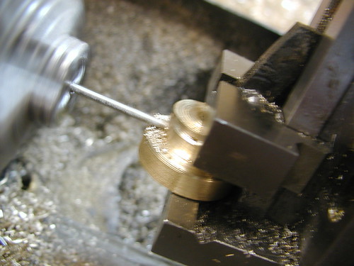
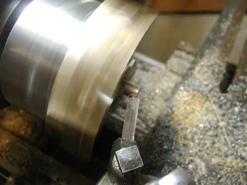
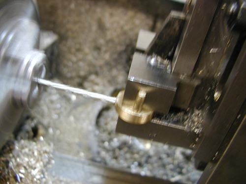
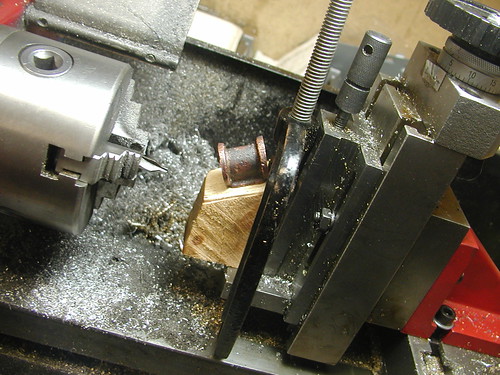
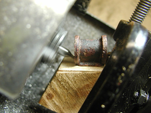
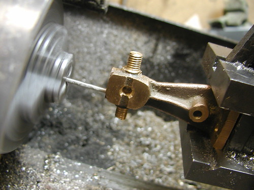
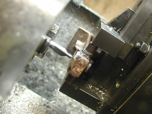
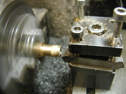
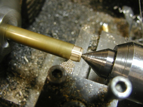
Since I had made the 12mm (1/2") American toolpost, I decided to put a big J&S knurling tool that came with the Hercus into use. For this operation, I ran the lathe in the slowest back gear to reduce the strain placed on the tool.
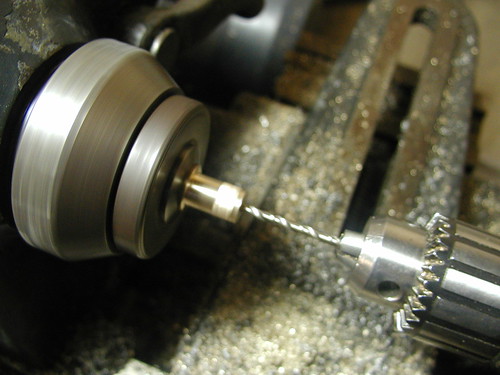
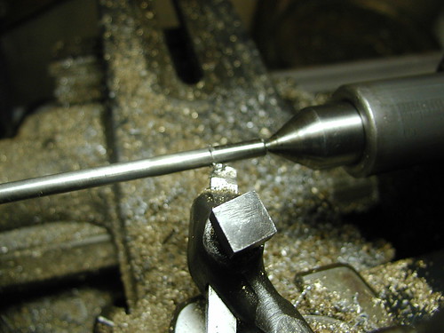
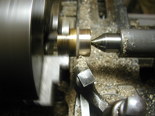
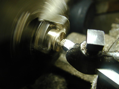
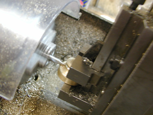
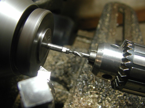
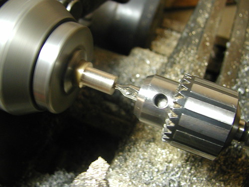
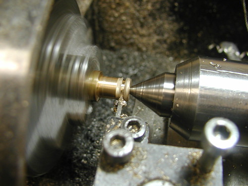
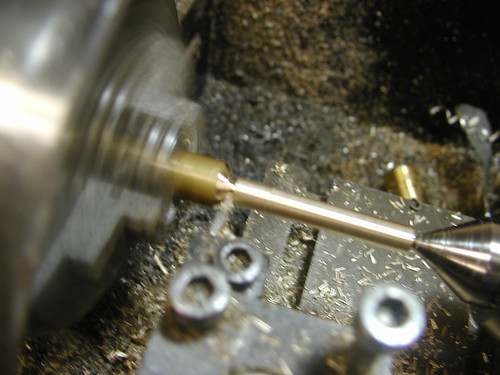
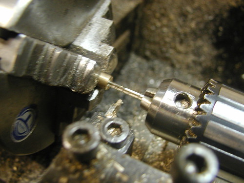
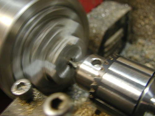
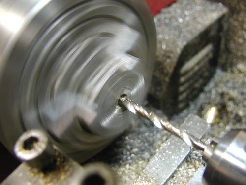
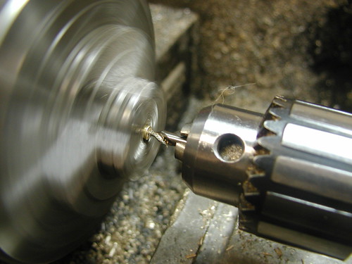
Drilling a 2.5mm hole to take an M3x0.5 tap.
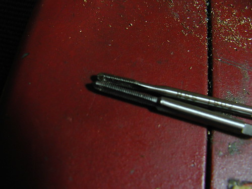
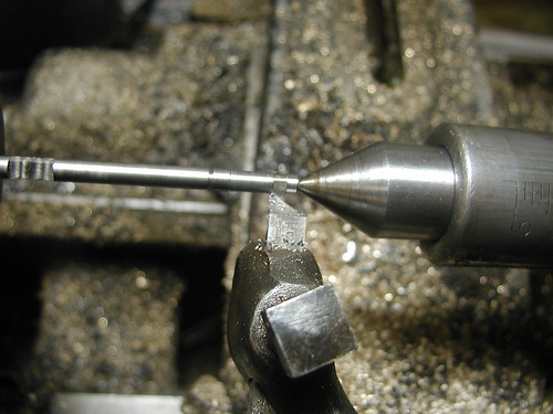
To tap my threads straight, I grip the job in the lathe, and grip the tap in the Jacobs chuck, and turn the Jacobs chuck by hand.
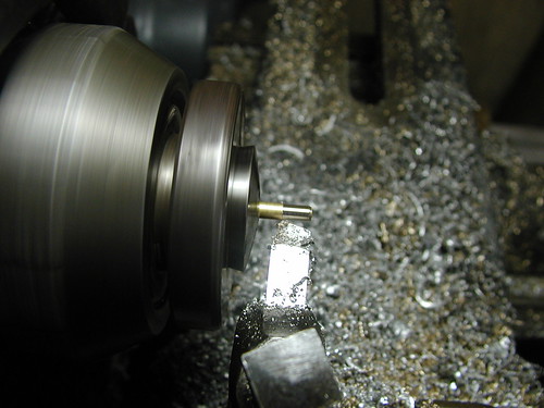
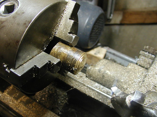
The workpiece was then transferred to the Sieg lathe and faced.
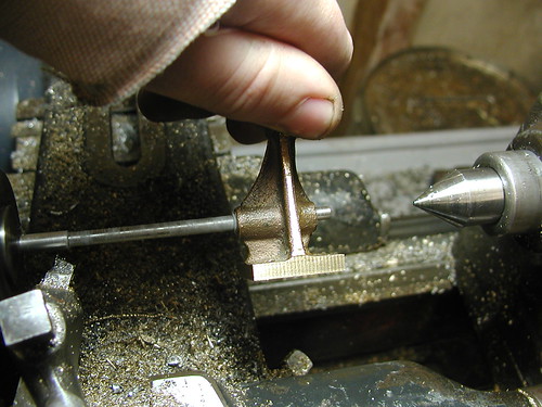
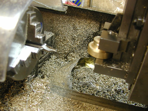
Finally, the nut is parted off.
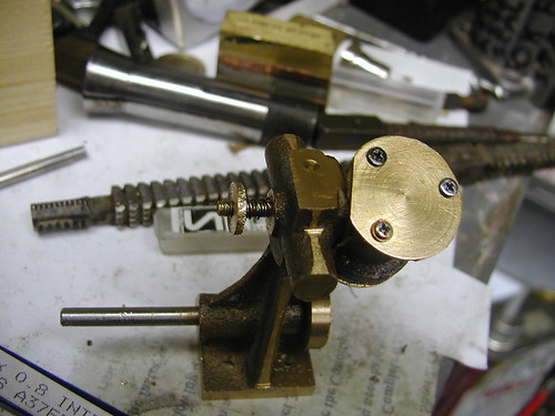
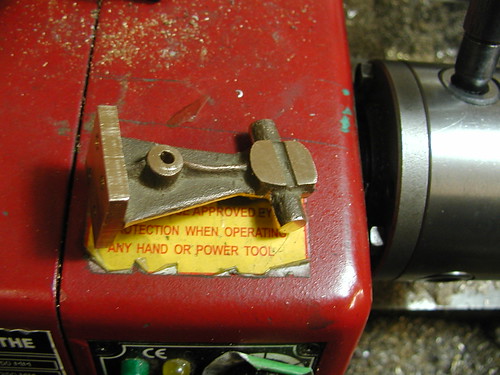
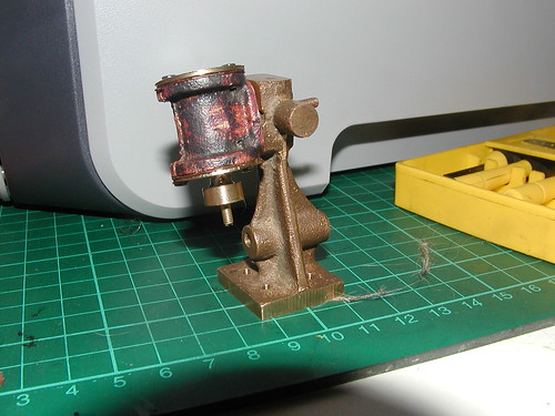
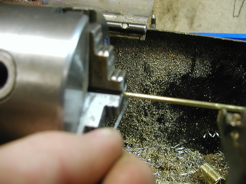
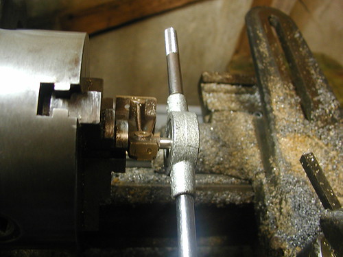
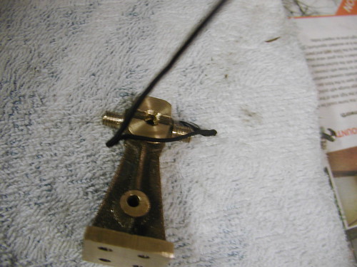
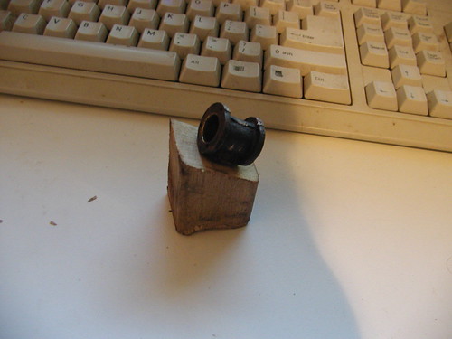
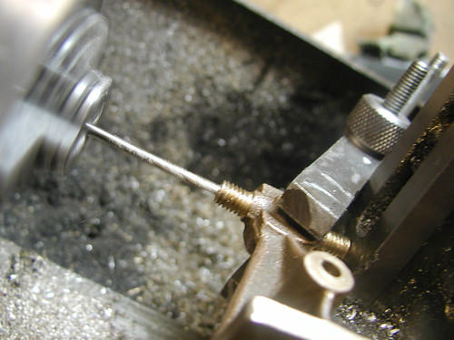
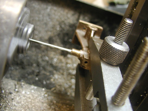
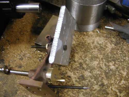
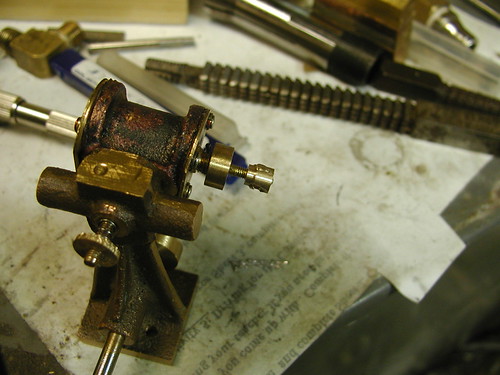
Here it is in place with a spring wound from some thin music wire.
Next came the big end. I started by facing another piece of brass rod. I did it in the Sieg lathe this time since the Hercus was having some belt trouble.
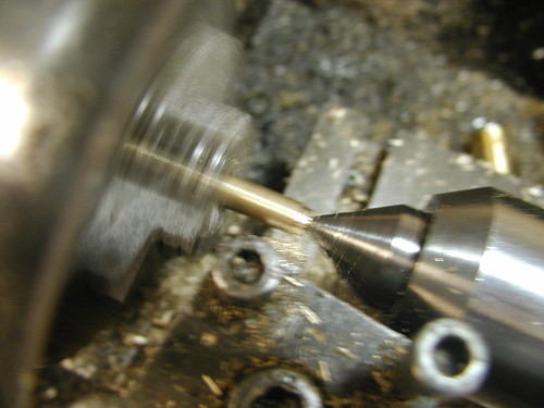
Centre drilling the end.
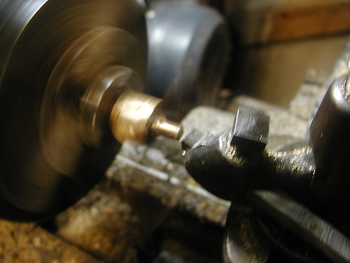
Turning a length down to diameter.
Parting off.
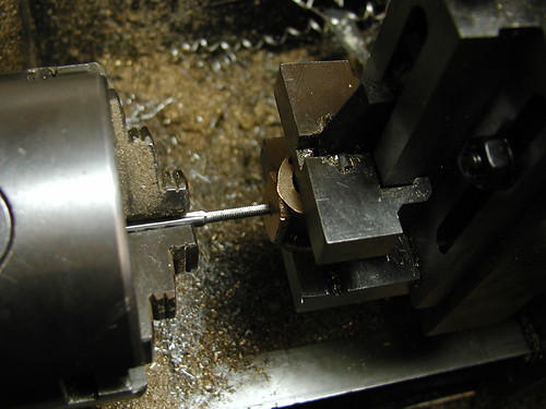
Drilling a 2mm hole to take an M2.5x0.45 tap.
Tapping the hole.
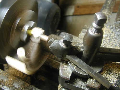
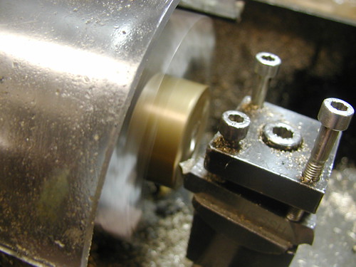
Turning the shoulder.
Parting the piece off.
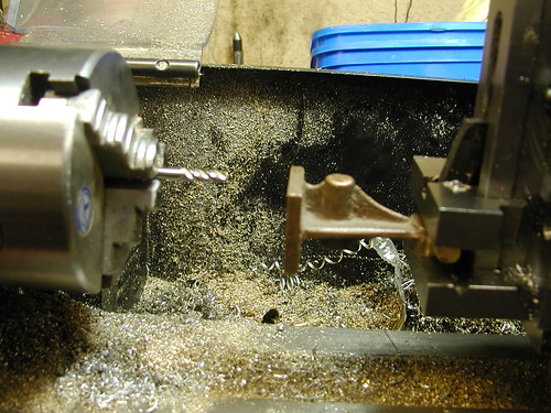
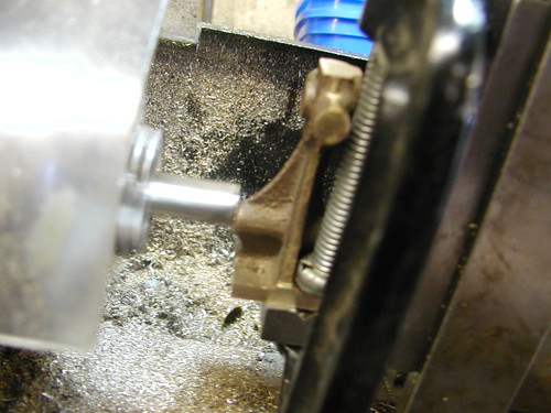
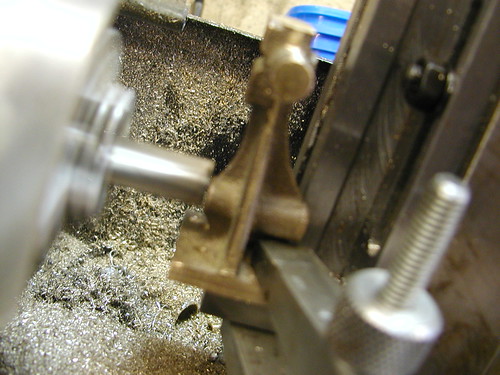
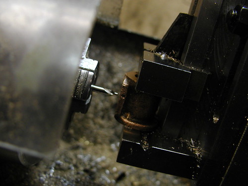
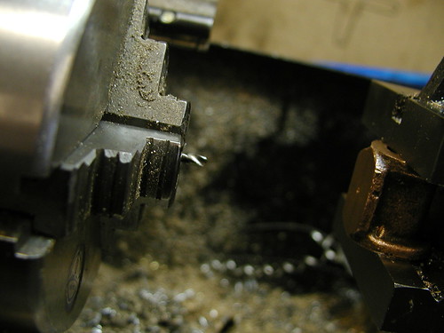
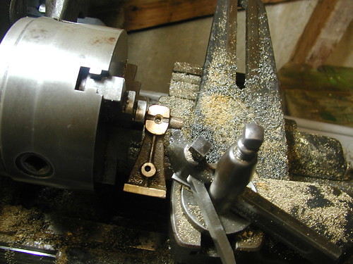
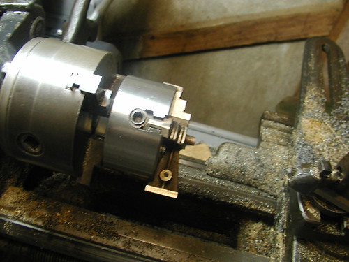
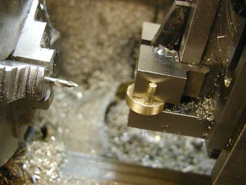
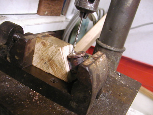
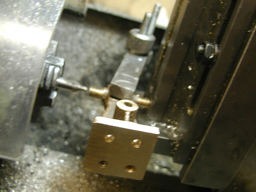
To drill the hole for the crankpin, the big end was set up in the 4-jaw chuck and flattened on one side with a 3mm end mill.
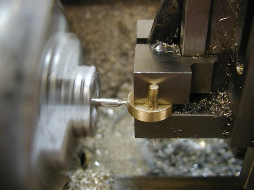
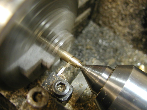
A centre drill was then used to start the hole.
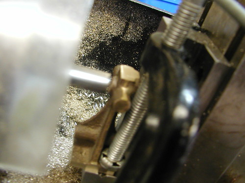
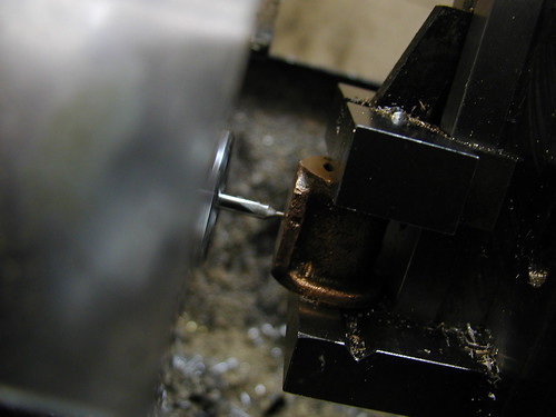
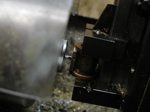
Drilling the hole to 1/8" right through.
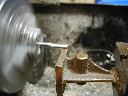
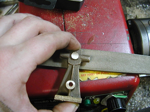
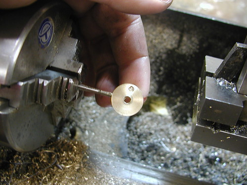
The finished big end in place on the engine.
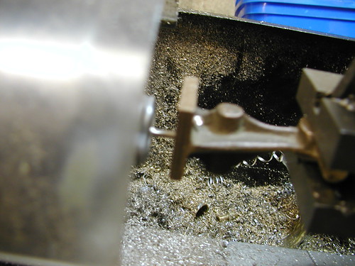
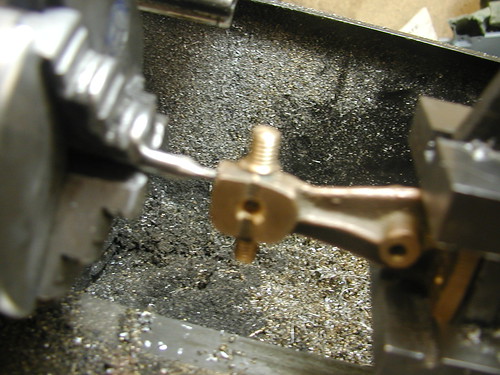
The crankshaft set up for drilling the web for the crankpin. The plans called for a 2-piece crankshaft made from cold rolled steel, but I have decided on a 3-piece design with a shaft made from stainless photocopier shaft and a brass web and pin.

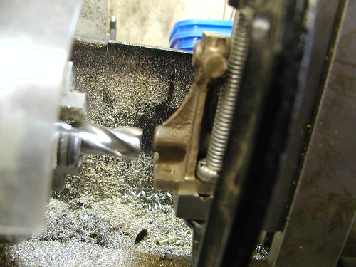
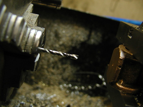
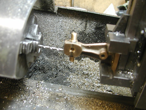
Starting the hole with a centre drill.
Drilling the hole to 3/32".
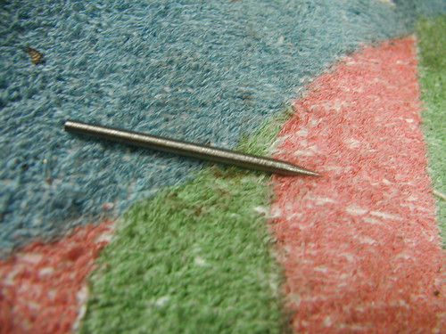
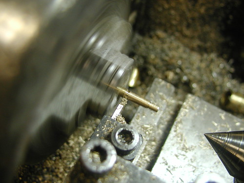
Next came the crankpin. I made this from a bit of thin brass rod I found at the scrapyard one day. First the rod is centre drilled.
Turning the rod down to a bit under 1/8" as per the plans.
Parting off.
Now for the flywheel. The plans called for this to be made from cold rolled steel, but I decided to make mine from brass. The workpiece was firstly faced.
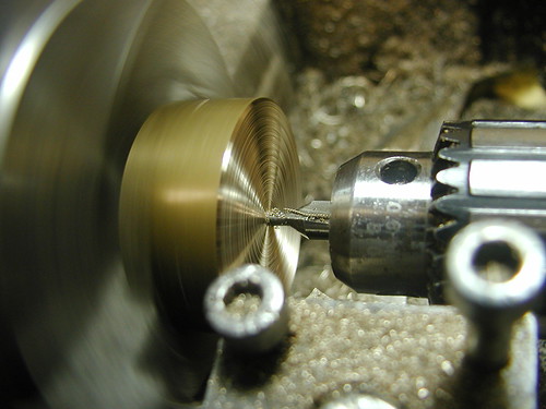
The hole through the hub was then started with a centre drill.

Then drilled to 4mm right through.

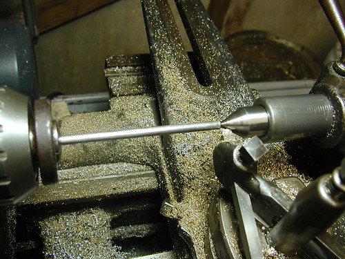
To do the rest of the machining operations, I decided to make a mandrel. First a piece of 6mm photocopier shaft is centre drilled.
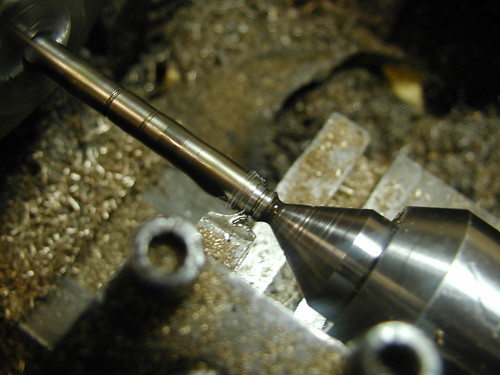
Then turned down to 4mm and threaded M4x0.7 part way down.
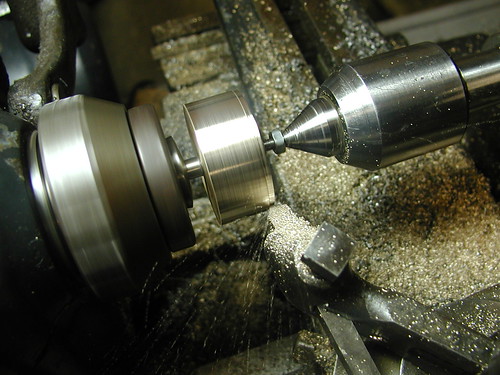
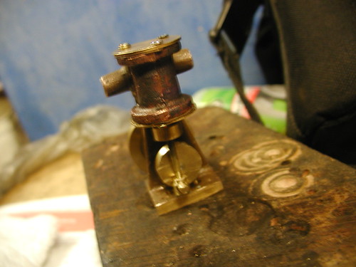
The flywheel is secured to the finished mandrel with a pair of nuts.
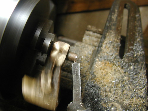
Turning the outside of the flywheel.
That's all for now, but an update should be coming soon.