


Tony Bird
Senior Member
Hi,
I recently completed a Stuart Progress model steam engines from casting.
According to the current Stuart catalogue their Progress, a model of a single cylinder horizontal oscillating steam engine with a ½ bore and a ¾stroke, was made for a short period in the 1930s.
Regarding the Progress what does your £80 including VAT buy? Well you get a cardboard box containing vacuum packed castings, lengths of brass and steel rod, nuts and bolts along with some graphite yarn, enough of everything to complete the model.
Instead of drawings you get a reprint of a circa 1913 booklet titled; The Stuart Progress model steam engines by S. M. Stuart Turner and Henry Greenly. So in the early part of the last century Progress was the name Stuart Turner gave to series of model steam engines that had components in common, mostly their cylinder castings. These model engines were as now supplied as a complete set of castings with other components to complete them, the cylinder castings then were supplied bored. So does Stuarts current catalogue mean that their Progress as supplied now was available as a completed model steam engine in the 1930s rather than a kit that was available up until that time?
In the booklet there are drawings and instructions for models of a single cylinder vertical and a horizontal oscillating steam engine along with four other single cylinder steam engines that used eccentrically operated valves. The final chapter has drawing of a suitable boiler to drive the models.
The Stuart references for their model steam engines described in the booklet are;
OV1. Oscillating Vertical No.1; a marine steam engine with a disc type flywheel.
OH1. Oscillating Horizontal No.1, (the steam engine that is being built). It looks like a mill engine and has a large flywheel with spokes.
SH1. High Speed Horizontal No.1, steam engine with a short stroke and eccentric operated valve gear.
HM1. Horizontal Mill No.1, steam engine with a longer stroke and eccentric operated valve gear.
SV1. Vertical Marine No.1 steam engine with eccentric operated valve gear.
HU1. Horizontal Undertype No.1, steam engine with eccentric operated valve gear and a boiler.
It would be preferable to have worked from a normal drawing of the model rather than a booklet containing other models. It was interesting to read of the construction techniques used in model engineers workshops a long time ago, workshops that used treadle lathes, hand powered drill and shaping machines with no mention of milling machines. The down side of the booklet is not having a complete drawing and instructions of the engine being built, where there are common components they are only described once so you have to keep changing pages so it is difficult to check dimensions to fit one part to another.
In the booklet the first engine described is the OV1 which shares the same cylinder and piston dimensions to the OH1 though the centre distance between the axle and the cylinder trunnion are different. The OV1 centre distance is 1.5/8which gives a 27 degree cylinder movement, the OH1 centre distance is 2 which gives a 22 degree cylinder movement.
The author always makes a drawing of the position of the axis of the moving parts of an engine being made; this is very straight forward on oscillating engines which have no valve linkage. So a drawing was made of both engines using the largest ports possible leaving no lap. The result shows that the ports of the OV1 at 2.5mm are 0.5mm larger than the OH1.
In practise a jig is used to position the ports in both the port block and the cylinder the holes drilled being slightly under size. After drill the distance between the edges of the ports in the port block is measured and sums done to work out the maximum size the ports can be leaving no lap. The ports are then drilled larger to suit the results of the sums.
The Stuart Turner instructions do not directly give the centre distance between the ports in the engines port block. They state that the distance between the edges of the ports must not be less than 1/8 and either 3/32 or 7/64 ports can be drilled. Out of interest some drawings were done of both engines using Stuart Turners dimensions. The results show that the OV1 has a lager valve opening and lap than the OH1. When running the OH1 should be smoother running because of its smaller lap. The author prefers using no lap on oscillating engines and on high speed oscillating engines even larger ports so that they effectively leak a little steam to exhaust, it happens so quickly that very little steam is wasted. The reason for doing this is not so much for the steam going into the cylinder but the exhaust steam exiting from it. With lap the valves close well before TDC trapping some of the exhaust steam in the cylinder; the less lap the less back pressure in the cylinder. In models having less lap it probably doesnt make that much difference to the power of the engine but it does make them smoother running.
Before a start was made on the Progress a further two drawings were made one to check that the steam passageways would miss the trunnion hole in the port block, the other to check the relative positions of the big end and the piston rod gland when the engine was at TDC.
First the cast iron box bed casting was cleaned up with a file and the flats where the engine frame would be attached machined.
The cast iron engine frame casting was tackled next and it was found to have chilled spots not unlike the Stuart S50 which had been recently been made. First the base of the frame was mounted in the milling machine but just blunted the milling cutter. The frame was then mounted in a 4 jaw chuck in the lathe and a ceramic tip tool managed to machine it. The frame was not the easiest shape to hold but except for the machining of the port faces which was done on a mill all of its machining was managed in the lathe using 3 and 4 jaw chucks. The hole for the axle was drilled in the lathe then the holding spigot was cut off and the hole for the trunnion drilled using a pillar drill.
After the engine frame was attached by bolts to the box bed the flywheel was machined and drilled. This was straight forward as the cast iron had no chilled spots and it machined well.
Next was the fly crank which alas was chilled and had several hard spots here again tipped tools managed to machine it.
With the flywheel and fly crank an axle was made so they could be fitted to the now undercoated box bed and engine frame.
The cylinder and its cylinder cover castings machined very well the cast iron being good. The cylinder casting is the same as the ones used by Stuart on their 10 range of engines without the ports cast in. After finishing the machining the sheet aluminium lagging cover was fitted to the cylinder.
A crank pin was fitted to the fly crank and a drilling jig was made to drill the ports in the port block and the cylinder.
As the drawings made showed that the steam passage ways should miss the trunnion bearing hole by nearly 1 mm there was no need to angle the steam ports outwards as shown on the drawing. As the steam and exhaust passageways were quite close together it was decided that the steam union would be fitted horizontally at the end of the port block and the exhaust union vertically on the top of the port block.
The jig was also used to position the ports to be drilled in the cylinder; holes for the passageways were then drilled from inside the cylinder to join the holes drilled for the ports.
With the cylinder body machined the cylinder coves were made. The casting of the gun metal gland for the piston rod wasnt very good and had no spigot to hold it while machining. According to the book of instructions the original casting supplied had one. So the gland was machined from brass.
The big end and piston were made from the materials supplied by Stuart the mild steel for the piston rod was replaced with stainless steel and the piston fitted with an 0 ring instead of soft packing.
This mostly finished the machining of Progress and after making the trunnion the engine was assembled; PTFE tape being used in the piston rod gland.
Unions were fitted into the port block along with a displacement lubricator and the Progress was run on air. The engine was quite stiff and needed quite a lot of pressure to get it going and it had a knock! It sounded almost like a big end knock. It was decided to run it in slowly with plenty of oil in the lathe. After an hour of this treatment there was a lot less resistance turning the engine over. Back to the air test and it still had a knock but it did run at a slightly lower pressure. A check was made that the piston wasnt hitting the cylinder cover which it wasnt. The problem was found by applying low pressure to the engine and turning it by hand; it was only working as a single acting engine! One of the steam passageways was blocked by some sealant that had been used on one of the holes that had been plugged. The noise was caused by the other side of the piston working as a pump and lifting the cylinder off the port block and the spring forcing it back. With the blockage removed the engine runs well at 8 psi and is one of the quietest the author has ever made.
The steam test had no problems just a little leakage between the cylinder and port block which should get less as they bed in.
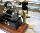
The Stuart Progress is fairly easy to build; it would be easier if there were up to date drawings and the casting were of a better quality. The engine is attractive and without a blocked passageway runs very well; it has been painted with Stuarts own brand of green and black paint. If another was built it would be interesting to increase the bore to ¾ which the use of the 10 series cylinder would allow. When the engines run in with its larger bore it should run on a very low pressure indeed.
Photographs to follow.
Regards Tony.
I recently completed a Stuart Progress model steam engines from casting.
According to the current Stuart catalogue their Progress, a model of a single cylinder horizontal oscillating steam engine with a ½ bore and a ¾stroke, was made for a short period in the 1930s.
Regarding the Progress what does your £80 including VAT buy? Well you get a cardboard box containing vacuum packed castings, lengths of brass and steel rod, nuts and bolts along with some graphite yarn, enough of everything to complete the model.
Instead of drawings you get a reprint of a circa 1913 booklet titled; The Stuart Progress model steam engines by S. M. Stuart Turner and Henry Greenly. So in the early part of the last century Progress was the name Stuart Turner gave to series of model steam engines that had components in common, mostly their cylinder castings. These model engines were as now supplied as a complete set of castings with other components to complete them, the cylinder castings then were supplied bored. So does Stuarts current catalogue mean that their Progress as supplied now was available as a completed model steam engine in the 1930s rather than a kit that was available up until that time?
In the booklet there are drawings and instructions for models of a single cylinder vertical and a horizontal oscillating steam engine along with four other single cylinder steam engines that used eccentrically operated valves. The final chapter has drawing of a suitable boiler to drive the models.
The Stuart references for their model steam engines described in the booklet are;
OV1. Oscillating Vertical No.1; a marine steam engine with a disc type flywheel.
OH1. Oscillating Horizontal No.1, (the steam engine that is being built). It looks like a mill engine and has a large flywheel with spokes.
SH1. High Speed Horizontal No.1, steam engine with a short stroke and eccentric operated valve gear.
HM1. Horizontal Mill No.1, steam engine with a longer stroke and eccentric operated valve gear.
SV1. Vertical Marine No.1 steam engine with eccentric operated valve gear.
HU1. Horizontal Undertype No.1, steam engine with eccentric operated valve gear and a boiler.
It would be preferable to have worked from a normal drawing of the model rather than a booklet containing other models. It was interesting to read of the construction techniques used in model engineers workshops a long time ago, workshops that used treadle lathes, hand powered drill and shaping machines with no mention of milling machines. The down side of the booklet is not having a complete drawing and instructions of the engine being built, where there are common components they are only described once so you have to keep changing pages so it is difficult to check dimensions to fit one part to another.
In the booklet the first engine described is the OV1 which shares the same cylinder and piston dimensions to the OH1 though the centre distance between the axle and the cylinder trunnion are different. The OV1 centre distance is 1.5/8which gives a 27 degree cylinder movement, the OH1 centre distance is 2 which gives a 22 degree cylinder movement.
The author always makes a drawing of the position of the axis of the moving parts of an engine being made; this is very straight forward on oscillating engines which have no valve linkage. So a drawing was made of both engines using the largest ports possible leaving no lap. The result shows that the ports of the OV1 at 2.5mm are 0.5mm larger than the OH1.
In practise a jig is used to position the ports in both the port block and the cylinder the holes drilled being slightly under size. After drill the distance between the edges of the ports in the port block is measured and sums done to work out the maximum size the ports can be leaving no lap. The ports are then drilled larger to suit the results of the sums.
The Stuart Turner instructions do not directly give the centre distance between the ports in the engines port block. They state that the distance between the edges of the ports must not be less than 1/8 and either 3/32 or 7/64 ports can be drilled. Out of interest some drawings were done of both engines using Stuart Turners dimensions. The results show that the OV1 has a lager valve opening and lap than the OH1. When running the OH1 should be smoother running because of its smaller lap. The author prefers using no lap on oscillating engines and on high speed oscillating engines even larger ports so that they effectively leak a little steam to exhaust, it happens so quickly that very little steam is wasted. The reason for doing this is not so much for the steam going into the cylinder but the exhaust steam exiting from it. With lap the valves close well before TDC trapping some of the exhaust steam in the cylinder; the less lap the less back pressure in the cylinder. In models having less lap it probably doesnt make that much difference to the power of the engine but it does make them smoother running.
Before a start was made on the Progress a further two drawings were made one to check that the steam passageways would miss the trunnion hole in the port block, the other to check the relative positions of the big end and the piston rod gland when the engine was at TDC.
First the cast iron box bed casting was cleaned up with a file and the flats where the engine frame would be attached machined.
The cast iron engine frame casting was tackled next and it was found to have chilled spots not unlike the Stuart S50 which had been recently been made. First the base of the frame was mounted in the milling machine but just blunted the milling cutter. The frame was then mounted in a 4 jaw chuck in the lathe and a ceramic tip tool managed to machine it. The frame was not the easiest shape to hold but except for the machining of the port faces which was done on a mill all of its machining was managed in the lathe using 3 and 4 jaw chucks. The hole for the axle was drilled in the lathe then the holding spigot was cut off and the hole for the trunnion drilled using a pillar drill.
After the engine frame was attached by bolts to the box bed the flywheel was machined and drilled. This was straight forward as the cast iron had no chilled spots and it machined well.
Next was the fly crank which alas was chilled and had several hard spots here again tipped tools managed to machine it.
With the flywheel and fly crank an axle was made so they could be fitted to the now undercoated box bed and engine frame.
The cylinder and its cylinder cover castings machined very well the cast iron being good. The cylinder casting is the same as the ones used by Stuart on their 10 range of engines without the ports cast in. After finishing the machining the sheet aluminium lagging cover was fitted to the cylinder.
A crank pin was fitted to the fly crank and a drilling jig was made to drill the ports in the port block and the cylinder.
As the drawings made showed that the steam passage ways should miss the trunnion bearing hole by nearly 1 mm there was no need to angle the steam ports outwards as shown on the drawing. As the steam and exhaust passageways were quite close together it was decided that the steam union would be fitted horizontally at the end of the port block and the exhaust union vertically on the top of the port block.
The jig was also used to position the ports to be drilled in the cylinder; holes for the passageways were then drilled from inside the cylinder to join the holes drilled for the ports.
With the cylinder body machined the cylinder coves were made. The casting of the gun metal gland for the piston rod wasnt very good and had no spigot to hold it while machining. According to the book of instructions the original casting supplied had one. So the gland was machined from brass.
The big end and piston were made from the materials supplied by Stuart the mild steel for the piston rod was replaced with stainless steel and the piston fitted with an 0 ring instead of soft packing.
This mostly finished the machining of Progress and after making the trunnion the engine was assembled; PTFE tape being used in the piston rod gland.
Unions were fitted into the port block along with a displacement lubricator and the Progress was run on air. The engine was quite stiff and needed quite a lot of pressure to get it going and it had a knock! It sounded almost like a big end knock. It was decided to run it in slowly with plenty of oil in the lathe. After an hour of this treatment there was a lot less resistance turning the engine over. Back to the air test and it still had a knock but it did run at a slightly lower pressure. A check was made that the piston wasnt hitting the cylinder cover which it wasnt. The problem was found by applying low pressure to the engine and turning it by hand; it was only working as a single acting engine! One of the steam passageways was blocked by some sealant that had been used on one of the holes that had been plugged. The noise was caused by the other side of the piston working as a pump and lifting the cylinder off the port block and the spring forcing it back. With the blockage removed the engine runs well at 8 psi and is one of the quietest the author has ever made.
The steam test had no problems just a little leakage between the cylinder and port block which should get less as they bed in.
The Stuart Progress is fairly easy to build; it would be easier if there were up to date drawings and the casting were of a better quality. The engine is attractive and without a blocked passageway runs very well; it has been painted with Stuarts own brand of green and black paint. If another was built it would be interesting to increase the bore to ¾ which the use of the 10 series cylinder would allow. When the engines run in with its larger bore it should run on a very low pressure indeed.
Photographs to follow.
Regards Tony.


.jpg")
.jpg")
.jpg")


.jpg")
.jpg")
.jpg")