The Frank Wiggins "S.T." double acting oscillator of 1943

Home Model Engine Machinist Forum

Help Support Home Model Engine Machinist Forum:

This site may earn a commission from merchant affiliate links, including eBay, Amazon, and others.

Kaleb

Senior Member
Joined
Jan 3, 2010
Messages
272
Reaction score
27
I've decided it's time to tackle building an engine from castings. So when this set came up on eBay, I thought it was just the thing to start with. Well, after waiting around 6 weeks, it finally showed up.


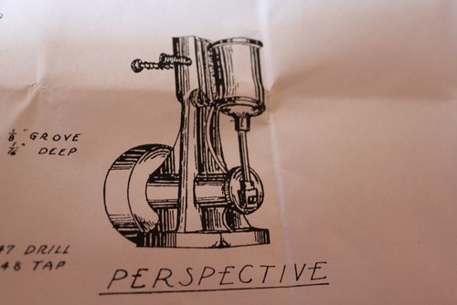
The designer's impression
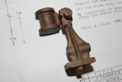
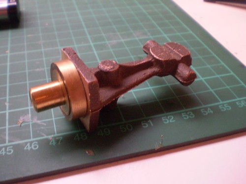


The raw castings


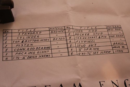
A list of all the parts


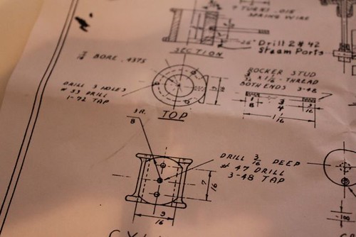
A view of the cylinder dimensions on the plans. 7/16" (approx. 11.1mm) bore and stroke.


Since the Jacob's chuck I have for my lathe can only take up to a 7mm drill, there won't be much room for a boring bar in there. So I bought this exquisite little Micro 100 from John Buckley. Paid a good $50, that's quality tooling for you!

This one should beep me busy for a good while, but hopefully it will be a little ripper of an engine if all goes to plan.
 
Nice little wobbler. Should keep you amused for a bit.
Brock
 
Made a start over the last couple of days. I decided to tackle the cylinder first, since getting it right could make all the difference.


Facing the port face. This face also becomes the reference.


The cylinder after facing and filing the port face and one end.

The two end faces of the cylinder must be absolutely parallel. I decided that the easiest way to achieve this is to make a fixture called a wax chuck. These are commonly used by clock and watchmakers. Here's a rough sketch to show the basic principle:


The adhesive is traditionally wax, but shellac, loctite and superglue will also work fine. Here's a walk-through of using one to make a part for a clock: http://www.snclocks.com/TechnicalInformation/Tid-Bits/Tid-Bit-2-Using-a-wax-chuck/4174805_W9qLsx#243895865_h4LDZ

I'll post some more details of making a wax chuck in a seperate thread. My next post in this build thread will show the results.
 
I also bought this same kit of ebay a few months ago!
It has been sitting in the drawer since and now i will be able to see what the correct
sequence should be!

Will be following along with you!

Andrew
 
Made the wax chuck yesterday, and it worked a treat.


The cylinder casting and wax chuck to the left


Both pieces solidly joined with superglue


All set up in the lathe


Facing the end of the cylinder


Facing done


The cylinder end face after filing


Heating with the blowtorch to part the glue


Workpiece off just before removing the remaining glue

Checked the end faces and they are pretty much spot on parallel, so the wax chuck has worked perfectly.
 
Nice! Will mentally file away the glue chuck technique for later!

Simon
 
Okay, with the ends of the cylinder faced parallel, it's time to bore it.

First, the bore centre must be found. I used a method suggested by John Buckley to locate it.


First one of the end faces is covered with ink. I don't have any of the special marking ink that others in the game use, so I used a black texta instead.


Next, the dividers are used to scribe a series of arcs across the surface. This is repeated at least 4 times, until all of them meet at a single point in the centre.


First arc scribed


The centre has been located and marked with a centre punch, and a circle has been scribed to roughly show the profile of the bore.


Now the cylinder is set up in the 4 jaw chuck with a piece of thin plywood to protect the port face. The jaws are adjusted until the centre mark is running true.


Centre drilling the cylinder.


Drilling a 7mm hole right through.


Boring the cylinder to diameter.


Done. I ended up with a bore of about 11.7mm, which is slightly more than what the plans called for, but it shouldn't matter too much. I'll simply make my piston bigger.

The cylinder will be put aside for the moment while I set about getting a tap and die of a suitable size for the cap screws. The plans call for a 1-72 UNF thread, but I'll probably use a metric one. M2x0.45mm is very close, but I might go smaller to be sure, maybe an M1.6 or something like that.
 
Hey Kaleb,

Getting everything square and parallel is never easy. It usually drives you nuts and can be very frustrating.

A technique to keep in mind while doing parts like this is to reduce the number of set ups. In saying that I mean, do as many operations on a part as you can in one chucking. It is "nearly" inpossible to set up on a surface twice , and although it can be done, it is made damn near impossible with very small parts.

For instance, do the bottom face and bore of the cylinder in one chucking because squareness there is very important to an engine. Then flip the part and face the top surface as parallelism of the top cover to the bottom, on a steam engine, is not that critical.

Now, there are other ways to skin the cat. You can bore the cylinder, and then mount it on a close fitting arbor and while so mounted, face both cylinder head faces parallel to eachother and, depending on how well you made the arbor, square to the bore.

Sometimes the error is very small, and to correct it only takes a .001-.002" of stock...but it helps later when you assembling the engine.

Just and observation and a albiet unsolicited piece of advice from the part of my brain that I've beat against the wall far too many times while trying to deal with small parts. File it away for the next part.

Looking good!

Dave
 
With the cylinder only needing a few more things done to it, I made a start on the frame casting a couple of days ago.


Cutting off the base of the sprue with the hacksaw.


The whole casting is then set up in the 4 jaw chuck like so.


Facing the bottom.


The resulting surface before finishing with a file. This surface also becomes the reference on this casting.

To face the top of the frame, I decided to use my shop made wax chuck again to make sure the two surfaces come out parallel.


Workpiece attached with superglue. This stuff really lives up to its name!


Set up in the lathe.


Facing the top of the frame.


Top surface faced and ready for finishing with the file.


While I was at it, I decided to file off some of the flash on the sides.

I paid a visit to a local optometrist to see if I could get some small taps, but he's willing to tap the holes for me if I bring the cylinder in. A very nice gesture, and it also means I don't need to buy any for the moment.

Next, I'll probably make and lap the piston and piston rod and lap the cylinder.
 
"I paid a visit to a local optometrist to see if I could get some small taps, but he's willing to tap the holes for me if I bring the cylinder in. A very nice gesture, and it also means I don't need to buy any for the moment."
What size taps are you looking for? The Optical repair kit I have has two taps 45/90 and 52/90 both of which are way smaller than anything I have used on a steam engine.
Regards,
Gerald.

 
steamboatmodel said:
"I paid a visit to a local optometrist to see if I could get some small taps, but he's willing to tap the holes for me if I bring the cylinder in. A very nice gesture, and it also means I don't need to buy any for the moment."
What size taps are you looking for? The Optical repair kit I have has two taps 45/90 and 52/90 both of which are way smaller than anything I have used on a steam engine.
Regards,
Gerald.

The plans call for 1-72 UNF which has a major diameter of about 1.8mm.
 
Where does it call for a 1-72UNF thread?

I made a couple modern ST oscillators earlier this summer which have pretty much identical dimensions in all the key areas as the old one you are building. the main difference is the standard and cylinder castings are shaped slightly differently. I just checked the plans, and the only threads it called for are 7BA, 5BA and 1/4x32TPI. The only one that got a little dicey was threading the hole in the face side of the cylinder for the stud on which the cylinder pivots, as there is not a lot of depth to work with. I can’t imagine where a 72TPI thread would be desirable on this model.
 
The 1-72 UNF thread is called for to fix the cylinder caps on.
 
Sorry for the delay in responding. If it helps, the modern S.T. Oscillator’s specify 7BA for the three studs/nuts that attach the top and bottom cylinder caps. I was able to get an airtight seal without using a gasket or reefing down on the nuts. 7BA works out to 52.91TPI which seemed plenty fine enough for the purpose. In planning ahead, you might want to look at the what is specified for the stud that the cylinder pivots on. The modern oscillator specifies 7BA for that too, but you need a very carefully bottom tap it so you don't end up with an unplanned hole in the side of the cylinder - and even then, you don't end up with a whole lot of threads.
 
Kaleb, where are you located? If you're in the US, I could send you some .010" teflon sheet for gasketing.
 
About time for an update on this project. I tried making a template for drilling the end cap screw holes, but was having all sorts of trouble. I left it for many months, but I now have a vertical slide for my Sieg lathe, which I used to drill the holes spot on.


The cylinder with its top end cap and screws. I ended up using an M2 thread for these, tapped into a 1.5mm hole. The end cap was a fairly simple turning job done on the Hercus, since I wanted to keep the Sieg set up with the milling attachment. The screws shown here were salvaged from an old floppy drive that was just kicking around gathering dust.


The end cap screwed in place on the cylinder. I've decided to make gaskets for both end caps from automotive gasket paper.
 
Things seem to be progressing well on your build Kaleb. If you do not have automotive gasket material already, an alternative is to use an old brown paper bag from the grocery store carry out. After cutting out and making holes, a light soaking with some sewing machine oil and a pat dry with a paper towel will yield a very useable gasket and at a fraction the cost of commercial gasket sheeting. Of course there is always teflon which is even better if you happen to have any about the shop.

BC1
Jim
 
Got the bottom end cap done today. Another fairly simple turning job. The thread has come out slightly wonky, but it should be fine since the hole is true.


Here it is mounted with the piston inside.


Another view from the side.

It's coming along well now, just need to file back the protruding edges of the caps, make the gland nut, do a bit more lapping, make and attach the trunnion, drill the porting and the cylinder will be done.
 

Latest posts

Back
Top