Team Design 1 - Cam Grinding Fixture

Home Model Engine Machinist Forum

Help Support Home Model Engine Machinist Forum:

This site may earn a commission from merchant affiliate links, including eBay, Amazon, and others.

wareagle

Well-Known Member
Joined
Jul 9, 2007
Messages
974
Reaction score
5
This thread has been started for the interested members to start the design of cam grinding fixture in response to this thead.

Sharpen those pencils and warm up those 'puters!

DISCLAIMER: The design(s) produced within this thread will be a joint effort between those members who wish to participate. Keep in mind that if you chose to follow any design herein that you do so at your own risk. HMEM is not liable nor responsible for verification of this/(these) design(s). In other words, the design(s) is/(are) unproven and may or may not be fully evaluated and tested for operation. Your desicion to build any of the designs herein indicates that you fully understand that the design(s) is/(are) not evaluated and proven, nor certified by a professional engineer.
 
Well,

I like the rocking beam versions as they are simple to get your head around.

I think cam followers are critical. They must match in geometry, if not scale with the followers used in the engine in question. but they can be very simple.

I think a few follower rests are in order also. Simple things, not complicated.

We should think about being able to grind crankshafts too. That would be helpful.

The big question is the spindle. There are several designs around on the web, most have been done in industry several thousand times, so article copywrite aside, the spindle designs are not patented.

Mr. Stevenson...this inversed one of which you speak...could you sketch that up for the group?

10-1 reduction will help for making a master as errors in the master will be reduced 10 fold on the cam. But I am concerned that the average Joe who is not up on cam design may have trouble making anything other than the cam he/she wants at a larger scale.

Additionally, 10-1 may result in a piece of equipment that is rather large ( maybe not). I am concerned that the average HMEM members machines may not handle it. We should decide on how large parts can be.


OK all....and there are others right? What say you?

Dave

 
Who's this Mr Stevenson ? :p

The 10" figure was just mentioned as being the one used on this model.
Cam follows are critical. Its no good having a sharp vee pointer following the pattern if the can has a radiused follower of it stuffs the geometry up.

I did a dirty sketch some while ago when I was explaining it to someone else, I'll check some old backups.

The spindle on this one was just an old Myford spindle running in two oilite bushings, it only has to run at 100 rpm I don't feel the spindle will be a problem unless you mean the grinding spindle ? The one on this machine was a commercial cartridge spindle mounted in two plumber type castings.

 
Hi John

Yes I was thinking of the grinding spindle. I agree the work spindle doesn't need to be sophisticated, but the grinding spindle needs to be pretty good to get good results. That means we're probably talking preloaded bearings and such. Not trivial.

Dave
 
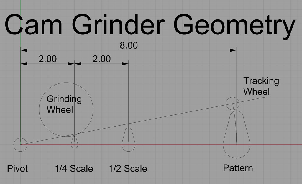
I tried a 10:1 reduction model on my CAD program and it seemed unweildy big. Here is the geometry sketched out for a 4:1 model:

CamGrinderGeometry.jpg


Imagine an arm the pivots from the pivot point shown. The pattern is at the far end, with a tracking wheel to follow it's contour. The wheel can be a bearing or other smooth tracking stylus. The model camshaft and grinding wheel are positioned at an appropriate distance based on how much it is desired to scale down the pattern. I've shown 1/2 and 1/4 scale positions here. Certainly things could also be scaled up to allow even more reduction.

In operation, the pattern and model camshaft are rotated at exactly the same speed while the grinder wheel takes its cuts. It is likely helpful to put the tracking wheel on a fine screw to control the depth of cut. The rotation of the camshafts can be managed with by hand crank or by a slow speed motor.

The whole affair can sit as shown with gravity holding the tracking wheel against the pattern, or it could be stood up vertical and a spring used.

For a spindle, there are lots of choices that aren't terribly expensive. A Little Machine Shop toolpost grinder would work great, for example. I am partial to the idea of designing it to stand upright so it can simply be used with a bench grinder. I suppose one could make a spindle for it if desired, but it seems unneccesary for something used as seldom as a cam grinder.

Best,

BW
 
I'll drop my $.02 worth... And that's about all it's worth! :big: And this will be a fun mind grinder!!

My thoughts for this design is to keep it simple and straight forward so the average home machinist could tackle it using as was said hobby sized equipment. If the machining could be kept to lathe and drill press work that would be even better. Use off the shelf components and keep the base and frame work easily adaptable for changes.

The inverted cam follower sounds very intriguing. I could see where setting up the follower with that design would be easier (maybe) to cut the master. If the design follows the normal route, then maybe an old automotive can lobe could be used as a master. Which gets me thinking I might have an old camshaft somewhere out of a small block Chevy. If I can locate it, maybe I can cut the individual lobes from it to use as master lobes. There'd be 16. And I only need one....

As far as designing it in mind for grinding crankshafts... I think that raises the complexity considerably. Maybe not, but I can see it doubling or more the amount of work to construct.
 
Here are some sketches of a grinder meant to be used with the tool grinders most of us have. The wheel is dressed to an angle because we need to approach it from an angle to get clearance.

CamGrinder1.jpg


CamGrinder2.jpg


This one is about 10" high and gives a 5:1 reduction from the pattern. Pattern and model camshaft are held between centers with lathe dogs. The brown framework pivots on the shaft at bottom to describe the arc. A follow on the fixed blue support tracks the pattern and moves the frame closer or further from the wheel according to the pattern's profile. There is a motor mounted on the pivot frame to drive the pattern and master at the same speeds.

This cam grinder could be built with drill press and lathe, but it would be easier with a mill. It's only a sketch, and there is a lot of detail missing. We first need to decide what format cam grinder to build.

Cheers,

BW
 
As far as designing it in mind for grinding crankshafts... I think that raises the complexity considerably. Maybe not, but I can see it doubling or more the amount of work to construct.

Agree. Why would one want to grind a crank by copying a master? I've never seen or heard of this being done (or am I misinformed?) All you need is to be able to offset the mains so that the big-end is concentric with the spindle - like they do it in 1:1

Got some qeustions, but I don't want to go O.T. I'll keep 'em for another time!
 
Still looking for the damn sketch.
The inverse pattern worked by replacing the follower on the plate by a scriber mounted at 90 degrees. A layer of tape was wrapped round the grinding wheel and the cam you wanted to follow was mounted on the headstock spindle.

Turn the drive motor by hand and it scribed the bit in the middle you had to cut out. Mine used 6" wheels and when they were worn to 5 - 3/4" they went on the bench grinder as this also affected the geometry but I am talking about copying cams for Manx Nortons etc which are probably a lot more critical.

Also I have probably misled you on the 10:1 ratio as the OD of the blank isn't critical only that it's round so you get an accurate base circle, the bit that's removed works out the ratio and it's got to be based on centre of the headstock to centre of pivot : size of cam or along those lines.

Really need this sketch. If I can't find it tonight I'll do another one, it far simpler than what has been sketched so far.

As regards a grinding spindle a bench grinder with work done on the bearing housings for float, although that's not critical but most important is the wheel mounting, balance and dressing should work OK.

I was given a very cheap 12 UKP grinder a while ago, not very powerful and only used for touching up HSS bits but when new this thing was dead smooth and would have made a good spindle. It's OK now but does vibrate but then again it's a shop tool, if I spent some time and a new wheel and probably a flywheel on the other end it would make a good grinder.
My cam grinder used steel bars for the pivoting bed and other bits, good cheap and sturdy given it will probably only have to do something like 6" to 8" long pieces max.

More later.
 
I've been toying with ideas the whole morning!! (distracting me from what I SHOULD be busy with :D )
I am thinking of ideas to keep the design and construction as simple as possible, as I don't think I would use it often enough to spend major cash and time on a dedicated grinding machine.

I am thinking along the line of making a fixture that will fit on the lathe. The cam blank should go in the machine chuck, with the other end supported in the tailstock. This already ensures accurate and solid job setup.
With the compound slide removed, the grinding fixture should now fit on the cross slide. The fixture should obviously include the master cam, with the master cam shaft driven from the chuck by whatever means: toothed belt, chain or whatever is lying around. One thing my mind is still stuck on is to get the drive to the master cam. - keeping in mind that the saddle must be moved to get from the one cam to the next. Spline shaft?? or a shaft with at least a keyway in that can slide through the master cam drive??

The grinding fixture should be lockable in a fixed position, so that one will be able to use it for a shaft grinder, controlling the cut size with the cross slide.

Only drawback I can foresee is ugly grinding dust on the machine bed, but I for one am perfectly willing to strip off the saddle for a proper cleandown after a grinding job. Like I said before, I don't foresee using something like this too often. (even if you use it once on every engine you build, it still isn't too often!!)

Ideas anyone?

I'll mock up a drawing when I get time (doubt if that's gonna happen :( )
 
Bob, I'm surprised you're not all over something like this
http://www.cnczone.com/forums/showthread.php?t=30633

A good start might be a review of existing designs; whats good about them and what's not.

you;re going to need a spindle. Bench grinder won't do. I has poor quality bearings and will leave a brutal finish. dremels and other such devices might be moderately better, but they're still a poor grinding spindle. I think you have to make one; maybe a preload with belleville washers or something like the quorn? at least with a light grinding spindle you can use a spring preload and don't have to buy matched bearings....still, as Dave says, not trivial. otoh, what about good tool making is?

You also need a precise way to index, but that could via template you cut with a dividing head.

personally, I'd make it free stand, keep the grinding grit well away from the lathe. I had a lathe once that was used a lot for grinding, not pretty.

I've made cams using the lowest tech method possible, working out the math to get the Z height for each part of a revolution and then milling the cam. you get a whole bunch of facets that are so small the blend together with one swipe of the smoothest of files. case harden and emery and you're done. Still, a cam grinder is a great addition to the IC engine builders shop

 
Carbide,
Here's what I make up for drive shafts, never seen it before but it's that simple someone must have thought of it before me.

ujshaft1.jpg


Just a socket with the 3/8" or 1/2" square bit cut off and pushed and brazed into the end of a tube.
Piece of hex bar selected to fit the socket [ or the other way round ;) ]

Same part in pieces to show build up.

ujshaft2.jpg


Made loads of these for special machines at odd times.

John S.
 
Mcgyver said:
Bob, I'm surprised you're not all over something like this
http://www.cnczone.com/forums/showthread.php?t=30633

Nah, that's an awful lot of work to go to unless you're going to R&D a whole line of IC engines!

I would cut the blanks on CNC mill, however.

I'm not too worried about my tool grinder. It runs very smooth and has demonstrated a nice ground finish before. Ought to work at least as well as faceting the cam on a mill. With that said, I've seen anough write ups on these Harbor Freight grinders to know that many probably are not operating that well. I got lucky on this one I guess.

BTW, here is a picture of a cam grinder very similar to what I'm proposing: http://www.mysterelly.com/IMAGES/CamGrinder_Detail0037alg.jpg

He really did use a bunch grinder and not even a Tool Grinder! Some aspects of that design are pretty nice.

Here's another CNCZone thread on cam grinding: http://www.cnczone.com/forums/showthread.php?t=3549

Swede (of the 5Bears site) makes a lot of engines and uses a hand cranked rig with his bench grinder as he mentions in that thread.

While we're on the subject of CNC, one could employ principles similar to the sketch I've given to eliminate the need for a model. It's a matter of mounting the model camshaft in a way so that it's rotation is properly synchronized to the motion of the mill table (not hard with a stepper motor for Mach 3 to control it), providing some form or fashion of grinding wheel at the spindle, and making the model camshaft springloaded so that the pressure on the cut varies as the mill is moving through it's cycle. If the springload doesn't turn you on it's also possible to just go very slowly with minimal depth of cut to get there: advance a thou, make a couple passes, advance another thou, etc..

A little Sieg CNC mill such as John works with ought to do the job very nicely and be every bit as sophisticated as the CNCZone project linked to. Plus you'd have a nice little CNC mill when you're done fooling with camshafts.

For the grinding spindle, I'd be prone to wanting to hang something like a toolpost grinder so the wheel is at right angles to the spindle. Or, if you have a surface grinder, you could likely place the Sieg rig right on the grinder and go from there.

Something like that is more the way I'd approach the problem in my own shop, but that's just my nutty CNC fetish at work. Simpler ways abound!

Best,

BW
 
well certainly Swede knows what he's doing, so maybe it will work.

Ought to work at least as well as faceting the cam on a mill.

I don;t think I'd posted a pic of the results, ??? maybe I'm wrong

anyway, have it, i look forward to seeing your cams roll off the production line
 
Hi guys,

You've been busy!.. I like what you guys have gotten to.

Pesky job thing is taking my time.....I'll post a bit tonight

Dave
 
Hi All.

I have read through what you guys dug up. There are some great ideas in there. I am glad you are all scouring your resources as this will help settle a spec. We can get out of feasabilty and into design.

BW you appear to have taken the bit and started running..Great!. I like your sketch and is the type of sketches we should be doing at this time
I think we need to get our ideas down and work out what we need. ( requirements)

From reading your posts I gathered the following

KISS is the word of the day ( Keep it simple....)

From what I read, CNC is not required, which I agree with as the amount of times I will be grinding cams will probably be relatively small

We need to keep the overall size as small as practicable for our members with small lathes/mills.
What do you think guys, what is the longest camshaft anyone will be grinding? 6" long? ( another question)

There appears to be some drive towards utilizing an existing grinder if possible. If we can adapt the design to an existing spindle, that would certainly be convienent. Should there be a spindle design for those who can"t do that? ( Thats a question too)

BW. That picture you posted shows a very simple fixture. It would appear that the cam just has a larger base circle than the one being ground. That is convienent from the perspective that you not locked into a reduction ratio. You just grind until you get the base circle diameter you want and stop. Very convienent.

It would appear that the ground cam has a proportionally smaller nose radius than the master, though that could just be the way the camera is angled. Additionally, the follower should have the same radius as the grinding wheel,( I think) That isn't that difficult but it is important.

I was also reading the CNC site. The comment that cam geometry is important should not be under stressed. I have seen a couple of model designs with flat flanks and that is not good. Very poor dynamic events with a flat flanked cam. From this, it is clear that the master/master follower must have good geometry.

BW, This is the arm with 10/1 reduction that I was thinking of. The pivot is in the corner, the cam 1/2" above it and the master 5" away from the pivot. This would give 10/1 reduction and keep the arm shrort. This may also allow the vast array of clutter surrounding the master to be away from a grinding wheel.
....All it is is one more sketch to the pile.....let's keep brainstorming...which is what we are doing right now. :)

Warms Regards,

Dave

camgrindingfixture.jpg


In any engine, the camshaft is the brain. It tells the valves when to open, how far to open, and long to stay open. There are other things to consider with cam lobe geometry, and that is to have the profile such that the valve train will become disconnected, in other words the tappets are leaving the surface of the cam lobe (spring pressures, lift, duration, RPMs, etc. all play a role in this phenominon as well, but let's focus on the cam itself). This can spell disaster if the conditions are right. The dynamics of cylinder fill, fluid pressures (air/fuel, steam, etc.), timing, displacement, intake and exhaust runner volumes, along with other design features of the engine can effect how a cam is best ground geometrically as well. For the purposes of this exercise, let's stay on track with the fixture design, and we can worry about the lobe geometry later. It truly is a science all by itself.

steamer has brought up a valid point in that we really need to have a target. A set of specs of sorts. With the different ideas we have here, this could very easily turn into a pair of designs, if not more. Like the saying goes, there's as many different ways of skinning the cat as there is people doing the skinning.

So, let's pick some design criteria (which has been started; let's just settle on some of the ideas, if you have more, throw them out here!) and let's get to working on a design. Once we come up with the specs, then we can put that into a post or even better, a document for future reference.
 
Hi

sorry I got confussed from the other thread :big: I didnt relise this was a full machine, does any one know if there is any vid's on one working so I can get some ideas on how these work?

Thanks,

Karl.
 
Hi guys,

Quick post

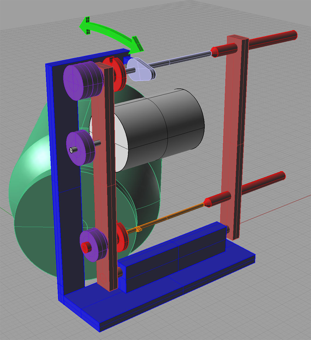
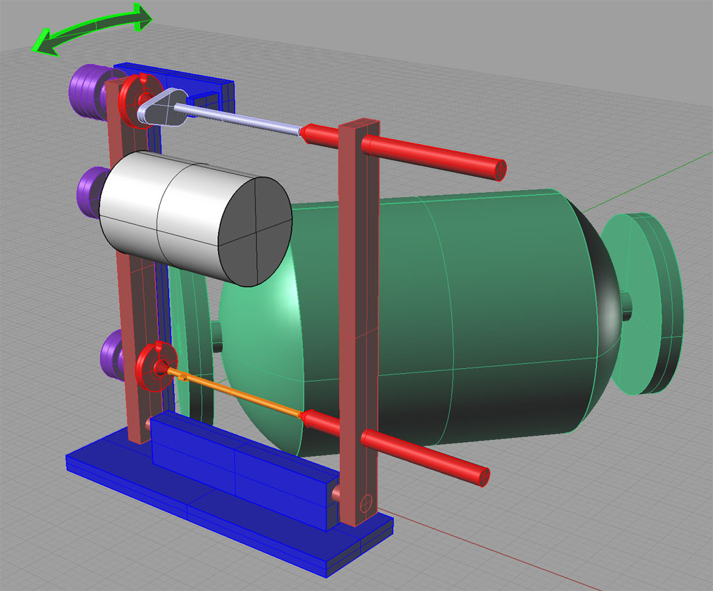
Heres a little more of the idea I had....sorry been busy around here.

CamGrinderproposal.jpg


The pivots are at the bottom and are outboard.

A pair of pulleys are to the left with the master cam in the back and the model cam in the foreground using the arms I showed in the previous post.
From the viewpoint of the grinding wheel

Lots more to flesh out, but it is the concept I am trying to convey.


Dave
 
I am having trouble getting my head around the angled design. Would the master came be an inverted profile? I guess it would depend on where you place the follower. Okay, never-mind. I answered my own question.
1261.gif


From what I see of this sketch, if the arms were flipped over with the angle pointing down rather than up, then the weight of the fixture would put the pressure on the grinding stone and cam blank. A "normal profile" master would lift the cam blank off of the wheel in this fashion. Flip the arms back to the above orientation, and you could use an inverted master. This of course assumes that the follower is below the axis of the fixture arms and we're letting Sir Isaac Newton provide our elbow grease.

Any thoughts??
 

Latest posts

Back
Top