Stuart triple - types of metals to get

Home Model Engine Machinist Forum

Help Support Home Model Engine Machinist Forum:

This site may earn a commission from merchant affiliate links, including eBay, Amazon, and others.
Robin,
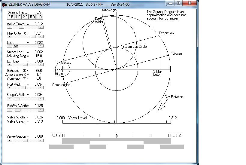
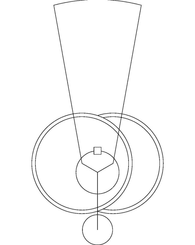
I do not have the Stuart triple but I do have a set of 6A castings and drawings. I will try my advise about the angle of advance on the 6A and report back. It looks like I was wrong as the Hp has a greater angle than the LP on the 6A so I should see more lap on the HP than the LP.

I also see that it looks like a D slide valve for all the cylinders. That is very important as the eccentrics would flip 180 degrees for piston valves.

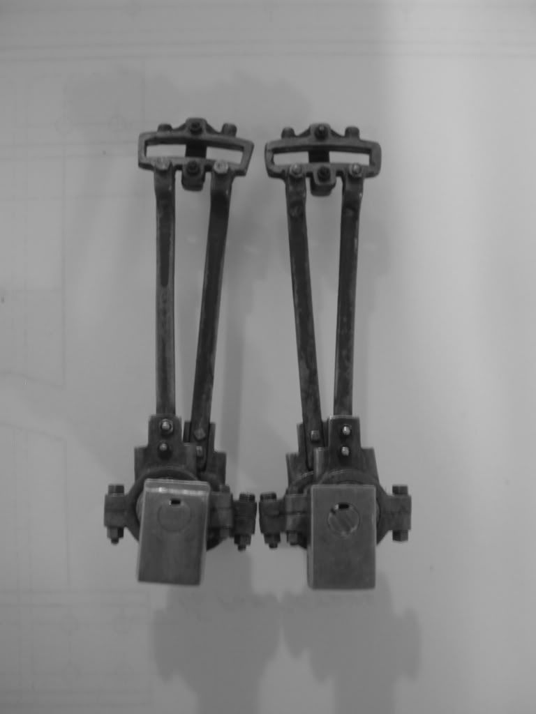
As for the eccentrics being reversed the photo tells the story. Lets just say that the photo shows the engine set for ahead operation. Now looking at the LP cylinder the ahead rod is closer to the bed plate and bearing. Now if we look at the HP cylinder we can see that it is the astern rod that is close to the bed plate. With a Shay the last part would be reversed. So yes the eccentrics are handed but they are handed the same way so my concern was not justified.

Dan
 
Robin,
I am posting the Bilgram diagram for the 6A which shows the valve and where to measure the lap which is the radius of the circle on a Bilgram diagram.

Now knowing only the information you provided, I drew a Bilgram diagram for the Stuart triple expansion.

This is why I feel that a Bilgram is so useful. I have answered your question that can be verified by the drawings using very little information from the drawing set.

I will post the information on how to construct a Bilgram diagram next on the valve diagram thread.
BilgramStuart6A.jpg

BilgramStuartTriple.jpg


The other important bit is where on the crank do you cut the key slot? I will draw a sketch that shows the correct orientation for Stephenson valve gear with D slide valves and open rods.

Dan
 
Don,

Wow, this is wonderful what you are computing for me.

The valves for the triple must be a little different than for your Stuart twin. I have attached a diagram of the HP valve and valve ports. In studying the drawings, the HP, IP & LP all share the exact same vertical dimensions for the ports and valves. the only differences I see is that the IP and LP are each progressively wider.

Does this change your belief that the LP is the one that gets the 30deg eccentric?

I figure I should locate the keyways at 180deg from that of the crank throw to which the eccentric belongs. In other words, if the piston is at TDC, the keyway will be at BDC. This give me the most meat to work with in the eccentric. The LP eccentric and flywheel will share the same keyway. And I'll extend the HP keyway to end of the shaft too. This might sound a little anal, but the only minor downside of this approach is that the three keyways will be 120deg out of phase with one another, which for the two outbound keyways might look a little odd. But I think function supersedes looks. Does this sound right to you?

Robin


valves.jpg
 
Robin,
The Bilgram diagram is a graphical calculator and like the more modern ones 'garbage in'... 'garbage out'.

Well I clearly blew it with the valve travel. I looked at the eccentric and my brain said 3/8" valve travel. That is just not true.
I checked the reverse gear for the Stuart 7A and there is a note for the throw of the eccentrics. The throw is half the valve travel and that is what is needed for the Bilgram diagram.

Can you tell me what is the throw of all the eccentrics?

Looking at the HP ports and valve the distance to the outter edges of the steam ports is 1/2" and the valve is 5/8" tall so the lap is half that distance or 1/16". From what you said the IP and the LP should have the same lap. That is why I am thinking different valve travel as the only thing left is the lead and that is usually very small or zero on a model.

The valve also has a bit of inside lap but that will not change anything. The 6A also has inside lap but I did not show it on the valve or the Bilgram diagram.

Dan
 
Dan Rowe said:
Can you tell me what is the throw of all the eccentrics?

Sorry Dan, I should have provided you the throw/valve travel. All three cylinders specify a 5/32" throw for the valvss, or a 5/16" travel (in the event you are having another blond moment that we all have from time to time). Other than the width of the ports getting wider from HP to LP, and two eccentrics being 15deg and the third being 30deg, I'm not seeing any other differences.

Robin
 
Robin,
No worries, I should have looked at the drawing more carefully instead of charging ahead with a bogus answer.

BilgramStuartTriple1.jpg


The % numbers are 100% piston stroke and the cut off as a percent of piston stroke. The 6A has 60% cut off for the HP and 85% for the LP.

That is why I now think that for the triple the HP has a 300 angle of advance and 80% cut off, and the IP/LP has a 150 angle of advance and 89% cut off.

The Bilgram diagrams show 1/64" lead for the HP and 1/64" negative lead for the IP/LP.

Dave AKA steamer or anyone else with triple expansion experience.....does that float or not?

Dan
 
Hi all

Sounds like the right neighborhood....ill need to review it to be sure

Generally, marine compounds and triples ran as long a cut-off as possible for maximum power and then relied on "linking up" to obtain economy.

Ill type more later

Dave
 
Dave and all,
I had my dimensions set to fractions for the lead not the best practice but I know that Stuart uses fractions in the drawings.

Anyway there are only two places to put the 300 eccentric on the HP or the LP. The IP is fixed at 150 because it is split.

Here are the Zeuner diagrams for the valve with both 30 and 15 degrees. Believe me it took longer to get the numbers with the Zeuner program. Well maybe not cause I did the Bilgram diagrams twice, but still I think cad and Bilgram is the way to go. I have nearly finished the post on how to construct one.

Dan
StuartTripleHP.jpg

StuartTripleIP_LP.jpg
 
The diagrams will tell you the cut off between the cylinders, but you will need to construct a theoretical indicator card (PV diagram) to determine the power developed in each cylinder as a function of cut off, compression, release ect. Generally, in small engines....you don't need exhaust lap as the parts are not going fast enough to need cushioning, and there is tons of condensate anyway.


Check out Cecil H. Peabody

The Thermodynamics of the Steam Engine

http://www.archive.org/details/thermodynamicsof004310mbp

He has a full set of equations to compute the theoretical idicator card for a triple and compound.

Dave
 
As per Stuart Turner print: The HP is 30° the others are 15°, Throw is 5/32"
All are same handed.
Hilmar
 
Hilmar said:
As per Stuart Turner print: The HP is 30° the others are 15°, Throw is 5/32"
All are same handed.
Hilmar

Thank you Himer and Dan for letting know which cylindre has the 30deg eccentrics.

Hopefully I can find some time to start making the eccentrics in the coming days.

Robin
 
rhankey said:
I figure I should locate the keyways at 180deg from that of the crank throw to which the eccentric belongs. In other words, if the piston is at TDC, the keyway will be at BDC. This give me the most meat to work with in the eccentric. The LP eccentric and flywheel will share the same keyway. And I'll extend the HP keyway to end of the shaft too. This might sound a little anal, but the only minor downside of this approach is that the three keyways will be 120deg out of phase with one another, which for the two outbound keyways might look a little odd. But I think function supersedes looks. Does this sound right to you?

Robin,
It was Hilmar that had the definite answer. My method would have worked if the lap for the valves were different.

As to the question as where to put the key way on the shaft well that really depends on where the key slot is cut in the eccentrics. It is normally in the thickest section. I made a sketch of the arrangement for open rods that are used for marine engines with link motion.


StuartTripleopenrods.jpg


I checked the reverse gear assembly drawing for the Stuart 7A and the crank pin is not shown and the eccentric does not have a key so the position of the crank pin is NOT fully specified in the Stuart prints. Checking the prints for the Stuart Cygnet which is really a 5A with an auxiliary package, I see the key on the crank is on the same side as the counter weight. This matches the sketch in this reply.

I hope that the print for the triple has a clear sketch of this issue because as I see it the photo you posted in reply #39 shows the engine has crossed rods.

I usually check Don Ashton's book on Stephenson link motion for the correct location of the crank pin for the various things that can change it like rocker or piston valves. In this case I also checked Peabody's book on valve gear and my sketch agrees with both books.

Looking at the photo it shows the HP cylinder at BDC just like the sketch, however the rods are crossed which is in my opinion is wrong. With the crank pin in that position the rods should be open NOT crossed as the photo shows.

My sketch is the way it is shown on the Stuart Cygnet and it is how a Shay would be assembled.

Dave thanks for the tip on Peabody's other books. I have a similar book by William Ripper but I know that Peabody was the head of the Marine Engineering Dept. at MIT and recommendations do not get much better than that. I will run the 6A design through the Peabody formulas. I found several of Peabody's books in new reprint form.

Dan
 
Dan,

Your diagram matches where I had intuitively planned on locating the keyways for each eccentric, which is opposite of the associated piston's TDC. I'm going to proceed with that.

Robin
 
Before I would key the parts, I would assembly everything and set the timing and then I would Key things. How do you set the timing if parts are keyed?
Hilmar
 
Hilmar,
Moving the eccentric changes the angle of advance. That is not the same thing as timing the engine.

As Robin already spotted there is only one correct way to set the eccentric if both eccentrics are made from the same lump of metal.

The best way to adjust the timing with a keyed eccentric that is common to Shays and marine engines is to adjust the length of the valve rod. Some engines had adjustable eccentric rods and the timing can be changed that way also but that leads to other issues.

I am thinking that this engine has a threaded upper end for the valve rod and that engages a nut on the rod that fits in the gap on the back of the valve.

To time a cylinder the gear is put in full gear and the lead is checked at TDC and BDC the lead is equalized for both BDC and TDC then the same thing is checked for full gear in the other direction.

Dan
 
Hiimar, As Dan points out, with forward and reverse eccentrics machined as a pair into a single piece of metal, no real adjustment of the eccentrics is possible. Rotating the eccentric to adjust timing for one direction, will hurt the other direction. As such, there is really only one position for the pair of eccentrics. If the eccentric were separated for each direction, I would definitely want to provide for adjustment.

And yes Dan, the length of the eccentric rod is adjustable with a nut at the valve. This won't correct advance issues, but will ensure the valve is centred over the valve ports correctly.

Robin
 
Robin,
The other thing I checked for the crank pin position was the eccentrics I mentioned. I had to separate one of them to make the other hand eccentric. I now use then for a drafting tool so I make double sure I never make the same goof again.

Here is the pair with both ends set at BDC. The screws for the blades and the saddles are 00-90.
DSCN3713.jpg

Dan
 
The three eccentric sheaves and the flywheel are done and all are keyed to the crankshaft, as can be seen in the attached photo. The eccentrics were almost as difficult and time consuming to make as the crankshaft, with each having three centres to be turned. One of the three eccentrics is split in half so it can be installed between two of the crankshaft throws. I had to draw a double size scale drawing to figure out exactly where to locate the two cheese head screws that hold the split eccentric halves together, as I opted to install the screws before I started machining the blob of metal that I’d cut in half. Fortunately, the holes and screws ended up dead on where they needed to be in the finished eccentric.

I'm almost afraid to mention how I broached the eccentrics and the flywheel, as some might disapprove, but it might come in handy for others. Being new to metalworking, I lack a press (among many other tools), and can think of numerous more basic "pressing" tools that I could make much greater use of. So, I misapplied my milling machine vice. By temporarily removing one of the large hex cap screws that hold the removable jaws in place, I was able to use the vice to drive the broach cutter through the bolt hole in the vice. The bolt hole wasn't quite as deep as the broach, nor was the travel of the vice jaws, so once I drove the broach halfway through, I'd back off, and slip the broach through a couple large sockets, then drive the broach the rest of the way through. The flywheel was too large a diameter to broach between the jaws of my vice, so I broached between the back side of the vice and a right angle plate, both of which I clamped to the milling machine table. This alternate method would allow me to easily broach a flywheel up to about 8" in diameter. The stainless steel eccentrics took a fair bit more force to broach than the cast iron flywheel, but I was amazed at how quick and easy it was to do the broaching. It took way more time to slot the crankshaft and to make and fit the keys. Hopefully this helps others who might have been afraid to try broaching.


IMG_8930 - Copy.jpg
 
It has been a while since I have posted any on-going progress photos, due in part to a little less time in the basement of late and slogging away on a lot of little parts that don't show for much. I have now completed most of the reversing gear parts as shown in the first photo. The second photo includes little oil cups that I added to the eccentric straps, which Stuart does not specify but seemed like a wise idea. Those 6 oil cups are so small, they all fit on a head of a dime. The eccentric straps and rods where much more time consuming than I would have anticipated due to the numerous very delicate machining steps required.

I feel like I still have much to learn, but with what I have built to date on this engine, I am feeling much more confident as i tackle parts now, and have a much better feel for what I am doing.

I think I will tackle the guide bar next, which mounts across the lower portion of the rear vertical columns. Then I will make the reverse shaft bar and the reversing crank shaft and crank handle. The reverse shaft specifies a rather small 2 start thread that I am now looking forward to tackling.

Robin


IMG_9626 - Copy.jpg


IMG_9633 - Copy.jpg
 
Very nice looking work! Can't wait to see this one progress more!
 

Latest posts

Back
Top