student_Machinist
Feist92
- Joined
- Jan 19, 2008
- Messages
- 86
- Reaction score
- 4
Heya
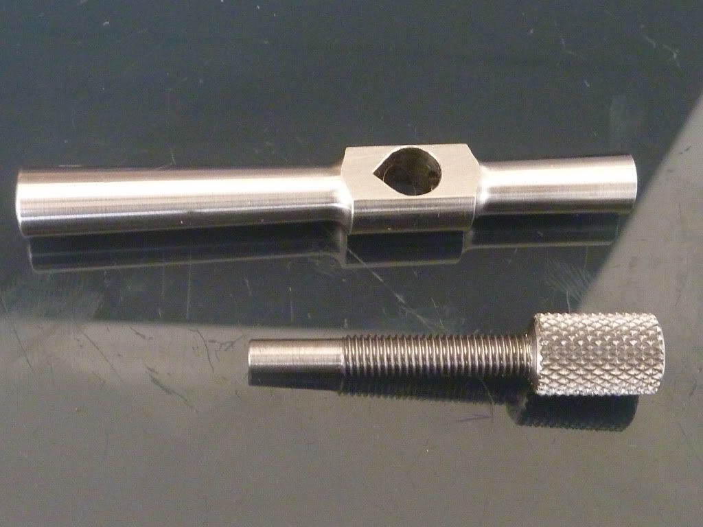
If any one has one would you mind filling in some of the measurements as show in the pic? I want to have a go at making one but want it to look right.
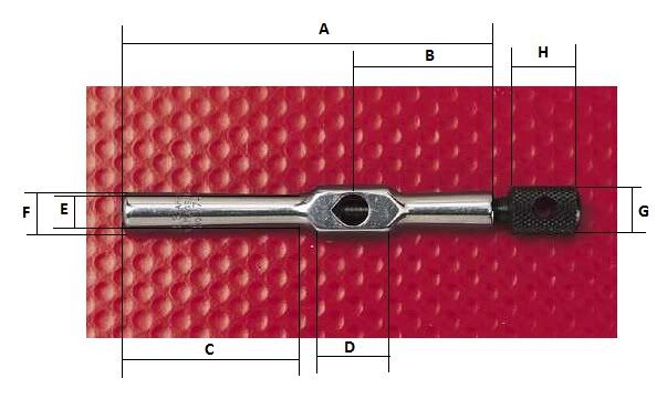
Just in case its hard to work out from the pic the measurements I need are:
A) Total length of the body
B) Distance from center of the hole to the short side
C) Length from the end of long side to the point where the taper finishes
D) Length of the middle section
E) Diameter of taper at smallest point
F) Diameter of taper at largest point
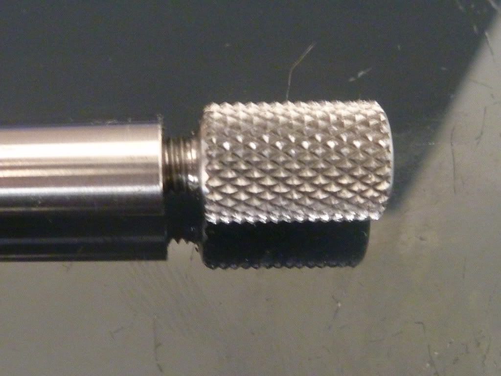
G) Diameter of knurled part of adjustment screw
H) Length Of knurled part of adjustment screw
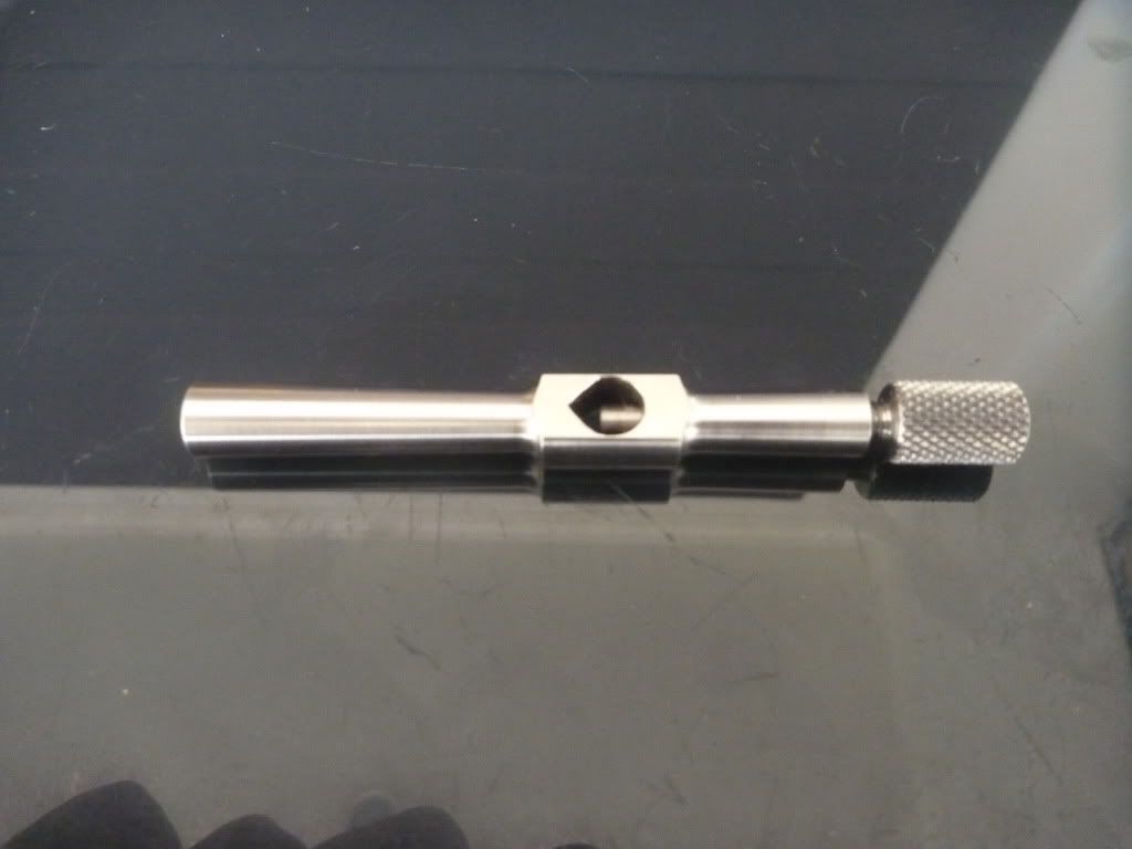
Not labeled on drawing.
I) Diameter of center hole
J) Diameter of hole in adjustment screw
K) Total length of adjustment screw
L) Thickness of flat center section
M) Diameter of the center section
I would really appreciate your help with this one, could be a cool little project and if it works out alright ill draw up some plans and post them on here. I reckon it could make a good first or second project for people starting out
BTW I dont mind if you measure in metric or imperial but I would like it to be reasonably accurate if possible
Cheers
Jonathan
If any one has one would you mind filling in some of the measurements as show in the pic? I want to have a go at making one but want it to look right.
Just in case its hard to work out from the pic the measurements I need are:
A) Total length of the body
B) Distance from center of the hole to the short side
C) Length from the end of long side to the point where the taper finishes
D) Length of the middle section
E) Diameter of taper at smallest point
F) Diameter of taper at largest point
G) Diameter of knurled part of adjustment screw
H) Length Of knurled part of adjustment screw
Not labeled on drawing.
I) Diameter of center hole
J) Diameter of hole in adjustment screw
K) Total length of adjustment screw
L) Thickness of flat center section
M) Diameter of the center section
I would really appreciate your help with this one, could be a cool little project and if it works out alright ill draw up some plans and post them on here. I reckon it could make a good first or second project for people starting out
BTW I dont mind if you measure in metric or imperial but I would like it to be reasonably accurate if possible
Cheers
Jonathan