


deere_x475guy
Well-Known Member
Well what can I say....I read about it here: (thanks again Cfellows!)
http://www.homemodelenginemachinist.com/index.php?topic=711.15
and had to try it.
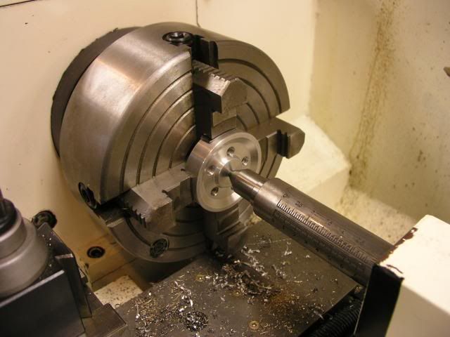
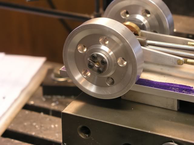
First thing I had to do was bore a taper in my flywheels. Got the 4 jaw out and did a quick center find with a dead center then refined it with a dial indicator.
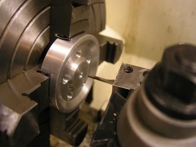
Next I found a 1/8" HSS blank that I had laying around and made a very tiny boring bar with it. You will see that because of interference with the tool post and chuck I had to cut from the back side with the tool upside down. I set the compound to 8 degrees.
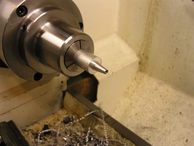
I did both wheels then without moving the toolpost from 8 degrees I cut the tapers on the bushings. I did this because I didn't feel confident that I could get the compound set exactly back to 8 degrees. If the tapers aren't perfect they won't do their job....don't ask me how I know. :")
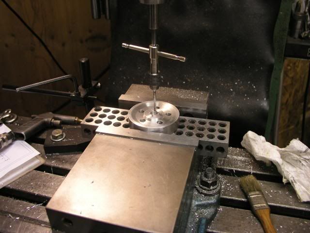
Next everything went over to the mill for drilling and taping.
And here is the final result:
It would have been much faster to just drill for a set screw and I had planned on doing just that until I read about the split bushing technique.
http://www.homemodelenginemachinist.com/index.php?topic=711.15
and had to try it.
First thing I had to do was bore a taper in my flywheels. Got the 4 jaw out and did a quick center find with a dead center then refined it with a dial indicator.
Next I found a 1/8" HSS blank that I had laying around and made a very tiny boring bar with it. You will see that because of interference with the tool post and chuck I had to cut from the back side with the tool upside down. I set the compound to 8 degrees.
I did both wheels then without moving the toolpost from 8 degrees I cut the tapers on the bushings. I did this because I didn't feel confident that I could get the compound set exactly back to 8 degrees. If the tapers aren't perfect they won't do their job....don't ask me how I know. :
Next everything went over to the mill for drilling and taping.
And here is the final result:
It would have been much faster to just drill for a set screw and I had planned on doing just that until I read about the split bushing technique.