Solenoid Motor Timing

Home Model Engine Machinist Forum

Help Support Home Model Engine Machinist Forum:

This site may earn a commission from merchant affiliate links, including eBay, Amazon, and others.

imagineering

Well-Known Member
Joined
Dec 6, 2010
Messages
96
Reaction score
14

I've seen a few Solenoid Motors on You-Tube and can't quite figure out the Timing.
Can someone who has built one, please enlighten me as to the number of Degrees before/after BDC the Points/Reed Switch should be triggered?

Murray
 
That's one of those "it depends" type of things. Switching latency, and time to build a magnetic field, will be the delay from the trigger event until force is applied, and as rpm builds, you will need to adjust in more degrees of advance for full efficiency. If your just interested in making a proof of concept or just something that spins around, start at TDC and it should work.
 
I usually make some sort of contact cam on the shaft of the motor and the experiment with a hand held piece of what I call brass shim stock. I say, what I call, because I have no idea. It is more copper colored and is quite springy and a little on the hard side. The stuff I use I picked up in a flea market, came on a roll about .014" thick and 1 1/16 wide. at about 4 ft. on the roll I have a lifetime supply. I usually cut a strip about 3/16" wide and a couple inches long to start with. Once I find the sweet spot, I either adjust the contact cam or location of the contact strip for a convenient location. I shy away fro micro switches as they tend to take much more effort to trip, sapping energy from the motor, I try different designs and styles, a lot of them based on antique toys. This is pretty much my typical contact setup.
HomemadeHorizSol.jpg

On this motor the solenoids were salvaged from an old electric motor starter. The amp draw is fairly heavy on these and I had some problems with the contacts pitting, so I mounted a pair of relays in the base, this seems to work well, although the hidden smoke escaped form one of the relays once. Not sure what caused it. There is one contact on each side of the motor. Just notiticed that the actual contact point is hidden from view behind the lever mechanism. It is a simple piece of triangular shaped brass sheet, sharing the same screw the connecting rod is attached to. Also the cam/crank is adjustable on the shaft to facilitate timing. The flywheel is a modified cart wheel.
 
Timing on these motors isn't critical although there is a point where the engine will run fastest. Depending on the type of switch you use, you can usually change the timing pretty easily by moving the switch (or points) closer or further from the cam.

Chuck
 
Can't speak for a solenoid motor - but in my other hobby - slotcar racing - the commutators are advanced to accomodate the ramp up time of the coils for optimum performance.

At 20000 rpm = no advance
At 120000 rpm = 45° advance.

Since a solenoid motor is going nowhere near this you don't need to worry about latency, hysterysis etc. etc.

So I would guess you set the switch points at the static switching positions and it should work fine.

If you are using relays - then the switching time of the relay could become significant - say 15ms switching time on a 600 rpm motor is equivalent to 54° timing angle. You obviously would want to use "high speed" relays - and if you can get the switching time from the manufacturer you can factor in the resultant timing angle for your desired rpm's.

Using solid state relays probably a better way to go.

You probably want to suppress the back emf from the coils (as well as the relay coils - if used) with blocking diodes or transorbs etc - this will also help preserve your switch points.
 
I forgot to add, the amount of time the solenoid is energized also comes into play. The contact strip I use is usually curved a little to keep it in contact longer making the power stroke longer. This effect could also be used with a longer high point on the cam in conjunction with a microswitch. Generally the power stroke can last pretty much the distance from BDC to TDC. A momentary contact usually doesn't produce as much speed, but can make for a nice slow running motor. A lot depends on the strength of the solenoid.
This is not a solenoid, but if you want a fun little project, this little guy will usually get more attention than a lot of much more sophisticated models and can be built in an hour. I picked this out of a very old Popular Mechanics. These can be finicky but can keep you amused for hours.
GUS
HomemadeTincan2.jpg

 
I am very interested in the tin can motor but can't see enough from the picture to see how it operates. I am assuming that the electromagnet pulls the ball bearing towards it and when released rolls around the can with the center bumper steering it around. But how do you time the electromagnet?
 
Timing these, just as for solenoid motors is a matter of trial and error.
Find a piece of fairly fine single strand copper wire, stiff enough to hold it's shape. Then hold it pointing at the solenoid and held into just far enough in to bump the ball as it passes and back far enough so the ball bearing doesn't grab on to the solenoid.
It will take some tinkering, but make a holder to approximate that position, from then it should only take some tweaking to get it to the sweet spot.
I usually end up with a slight arc bend on the wire to adjust contact time and release point. You don't want the wire to impede the travel of the ball. The ball bearing can be any size that will keep momentum and still hang on to the rim of the can.

GUS
 
Last edited:
This is not a solenoid, but if you want a fun little project, this little guy will usually get more attention than a lot of much more sophisticated models and can be built in an hour. I picked this out of a very old Popular Mechanics. These can be finicky but can keep you amused for hours.

This is a cool looking little project that looks like I might be able to do with my kids. Can anyone point me in the direction of some plans? I tried searching but I don't even know what it's called. Thanks.
 
I'll dig them out and post some close ups. Hmm, now If I can find them.

If I remember correctly, the article was very incomplete.
Construction details would depend mostly on what parts you can conjure up.
The can should be the easy part.:rolleyes:
GUS

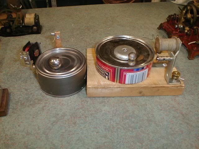
Just went back and looked at the pictures I posted previously, the one on the right is pretty much what the magazine showed.
The other was a really simplified version.
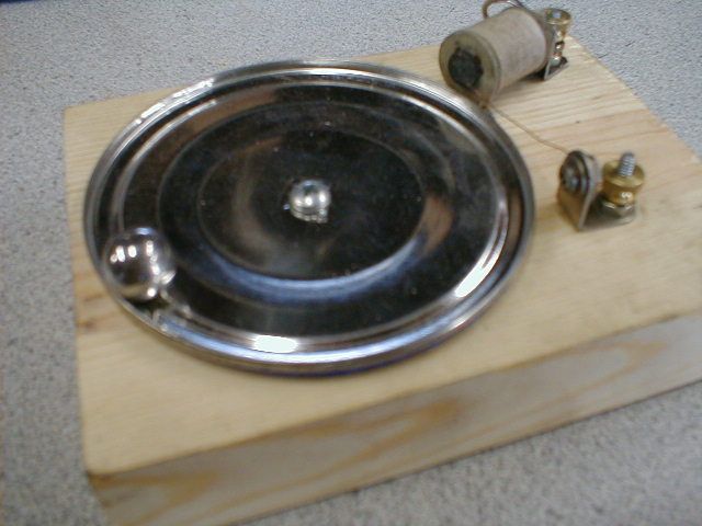
I had one with a guardrail to help keep the ball in the arena.

These pics are in my puter. Here's the opposite side:


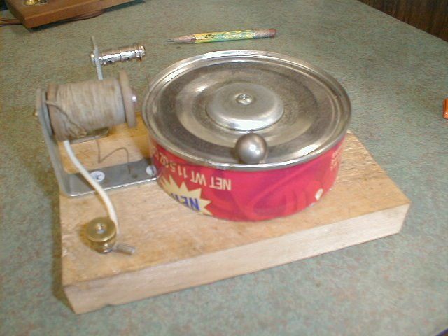
This is a very simple version. The coil is hooked to a battery (battery size depends on trial and error, usually one or two D cells), it doesn't take a lot of voltage. The remaining wire of the coil connects (under the base) with he fine wire on the right, which is the trigger wire and grounds the ball to the can lid to complete the circuit.
Although it looks it, the trigger wire does not contact the contact the core of the coil.


Just noticing, on the first pic, the coil lead is soldered to the can lid to and the trigger is the ground. Doesn't much matter how you configure he circuit.
 
Last edited:
Just an add on to my much edited previous post.

A ready coil source is a low voltage bell or buzzer, flea market stuff.

Another note: the trigger wire is expendable as is the ball and can lid. They all suffer tracking from the small spark emitted on contact surfaces and eventually develop poor contact.
The ball will usually develop a definite contact pattern around the circumference.
GUS
 
Back
Top