Small valves with manifold completed

Home Model Engine Machinist Forum

Help Support Home Model Engine Machinist Forum:

This site may earn a commission from merchant affiliate links, including eBay, Amazon, and others.

gbritnell

Project of the Month Winner!!!
Project of the Month Winner
Joined
Jul 16, 2007
Messages
2,985
Reaction score
1,052
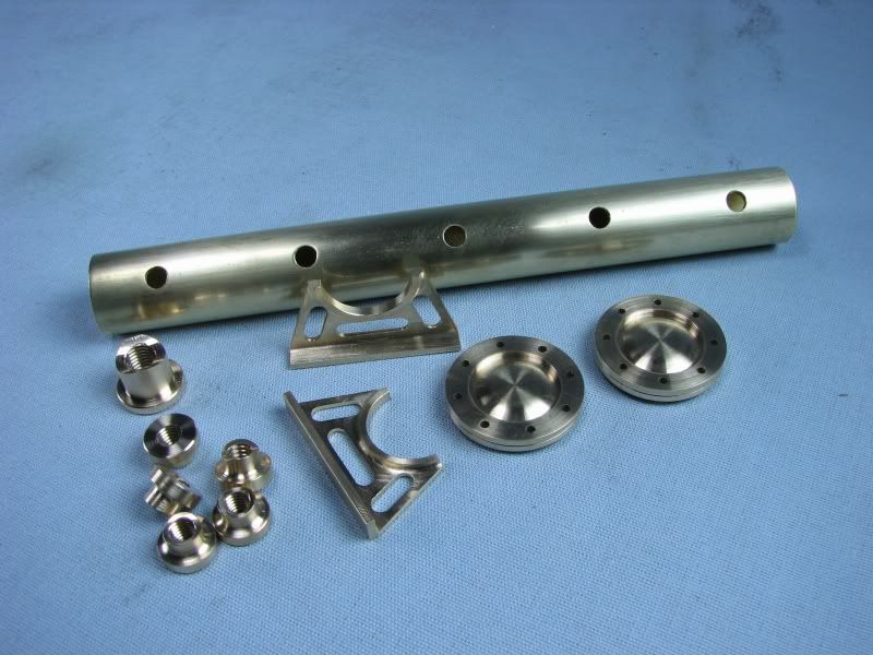
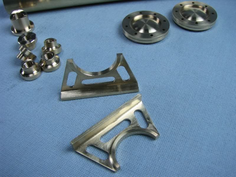
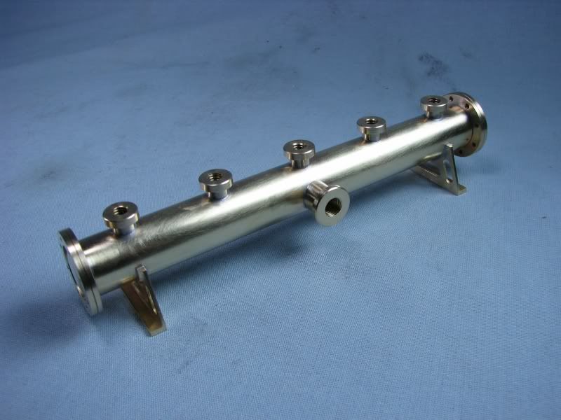
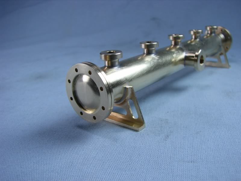
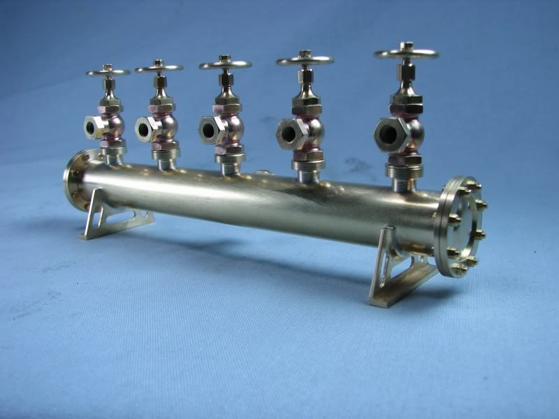
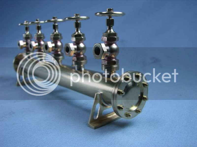
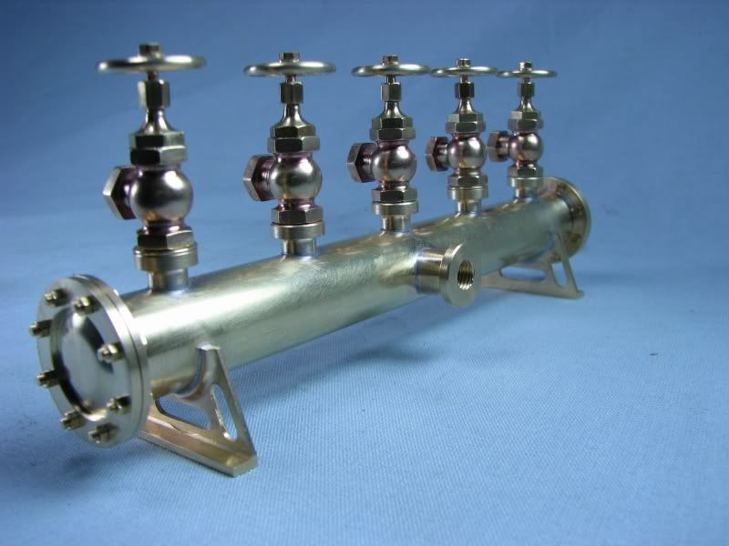
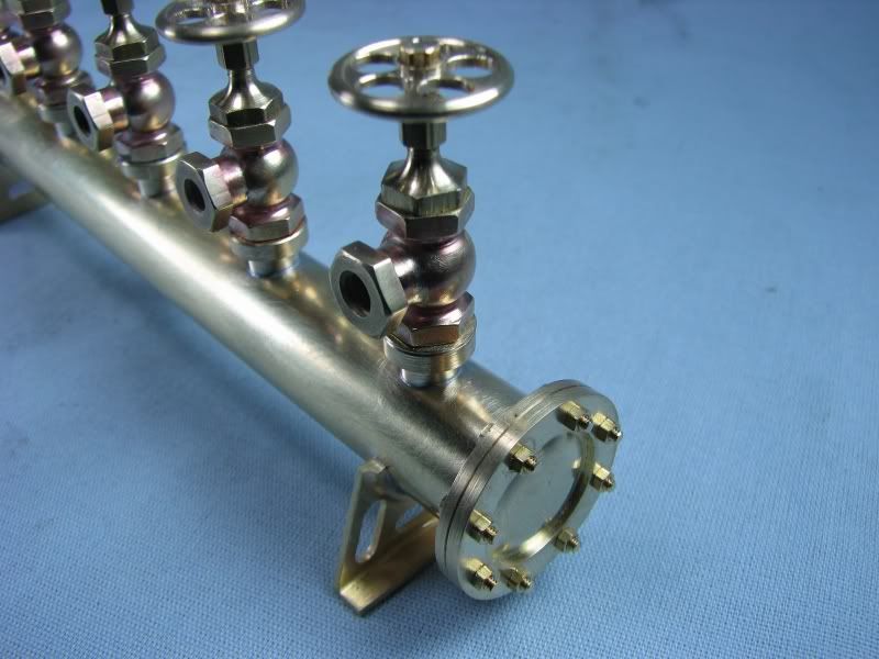
Here's a follow up to the small globe valve thread. As I had mentioned I have been using a manifold with aquarium type valves on it to distribute compressed air to my models when I exhibit them. It worked ok. but just didn't fit the part so I started on this project. I wanted something industrial looking to fit my engines. I started with a piece of .625 brass tubing for the manifold. I then made up the valve bosses along with the internal sleeves to locate them to the manifold when soldering. I then made the end caps and decided to put 0-80 bolts into them to make them look like a high pressure pipe cap. Next I tried to figure the best way to make the legs. I could cut them out of a piece of flat brass stock, solder them to another piece of stock, set them up on my rotary table and whittle them down or I could machine them onto the end of a piece of 2.00 round stock that I had and then saw them off in the mill. The second option seemed like less work so that is how the legs got made. The manifold was then drilled for the bushing size, everything was assembled and fluxed and then soft soldered together with 50/50 solder. After soldering I cleaned everything up with an old toothbrush and powdered copper cleaner, the type for cleaning copper pots and pans. The valves were then installed and shims were made to get them all properly lined up. All I have to do now is make the spigots for the air lines to slip over.
gbritnell

MANIFOLD1.jpg


MANIFOLD2.jpg


MANIFOLD3.jpg


MANIFOLD4.jpg


MANIFOLD5.jpg


MANIFOLD6.jpg


MANIFOLD7.jpg


MANIFOLD8.jpg


Very Nice. Like the flanged end caps, nice touch.
 
That's nice wow. do you have reference for size please

very nice well done
 
I really like that.
 
Really an impressive set-up.

Did you nickle plate the brass, or is it the lighting? If plated, what did you use?

Dennis
 
Hi Dennis,
It's just the lighting. I use daylight flourescent bulbs in my photo setup because they are supposed to be closer to sunlight so it knocks down the warm side of the spectrum.
gbritnell
 
gbritnell, thanks (once again! :bow:) - I love the legs for the setup; "simple", but so exquisite!

Apologies for being a newbie - You say you soft-soldered with a 50/50 - is that like 50% tin / 50% lead solder - like for electronics etc. ?

Regards, Arnold
 
Great work!!!!!! :bow:

Ian (seagar)
 
Arnold, you are correct. If there was any great pressure involved I would have silver soldered the whole affair but being as there won't be more than 20-30 lbs. of compressed air in it, it will hold just fine. Each of the flanges has a ferrule inside of them and the endcaps have a .04 boss that goes into the tubing so with the solder they are quite secure.
gbritnell
 
Wow, nice brass. A day with a dremel and some brasso soaked felt cones and it would substitute for a fun house mirror. ;D I really like your idea of making the auxillary support gear 'match' your engines.

Kermit


Great work!!! :bow:Very interested in your valves... are there plans available for these valves?
I am currently building a 1/16 scale Otto Langen Atmospheric Engine. I would like to in corporate this valve design into some of my auxillary piping.
Thanks
 
Truly a work of art. The big trick in doing something like that is making so many peices exactly the same. It looks good, and for my money it requires as much or more skill to build that than to make a small engine.---Brian
 
gbritnell

Definitely a work of art. It looks much bigger than it really is. Another piece that you can be proud of. :bow:

Cheers

Don


Latest posts

Back
Top