Six Shooter Elbow Engine

Home Model Engine Machinist Forum

Help Support Home Model Engine Machinist Forum:

This site may earn a commission from merchant affiliate links, including eBay, Amazon, and others.
arnoldb said:
a libation of Namibia's finest should add to the mollifying effect.

Three in fact Arnold.

Just get back on the horse........

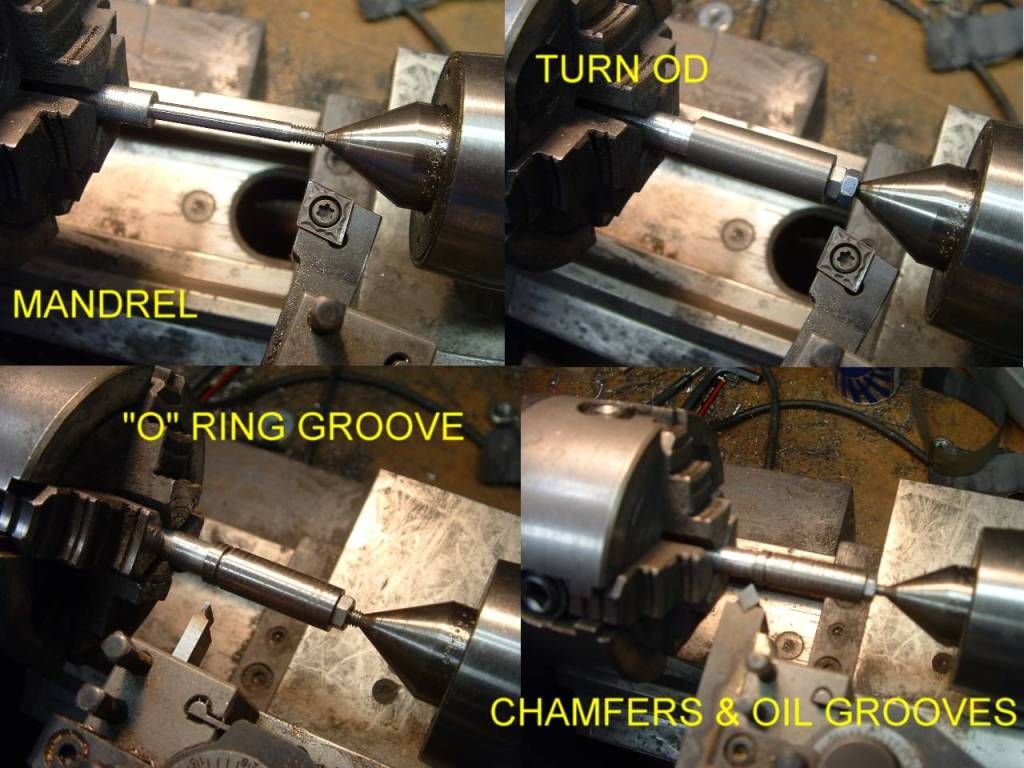
Finished the the distributor axles.
eb6anulus.jpg


Top left - drilling the ports & M3 mounting holes.

Then stand the RT upright without removing the part to retain angular alignment - a PITB as you have two parts to do but definately the safest way.
Top right drilling the port cross hole.
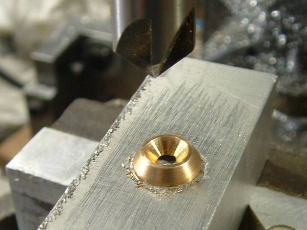
Bottom left machining the annulus groove 120° either side.
Bottom right - plan ahead. I have done this before where after meticulously clocking up the work etc. you then find you can't gain access with the cutter - lesson learned.

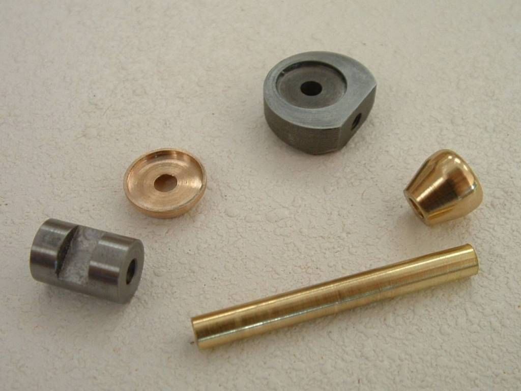
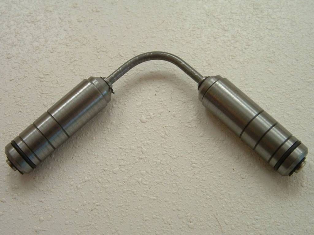
The finished axle(s).

eb6shaftb.jpg


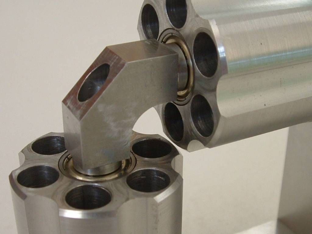
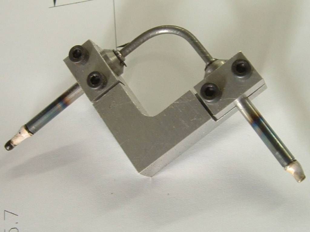
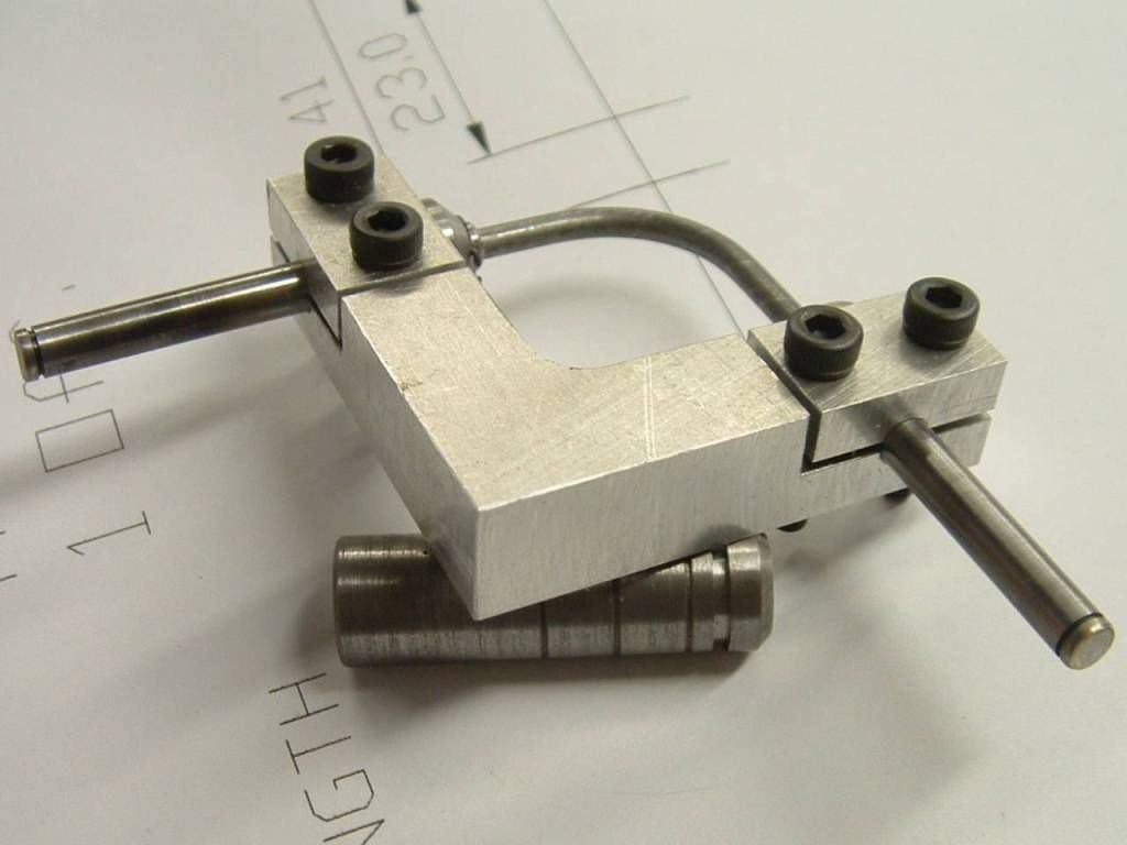
Trial assembly of the cylinders - its starting to look like an elbow engine.

eb6triala.jpg


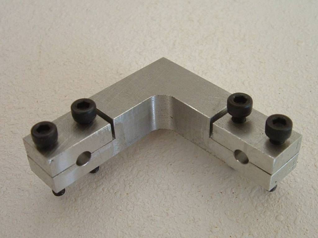
So far so good now for the stiffener bracket.

For some reason I've been putting off the "production run" of 12 pistons, 12 elbow axles, 12 elbow shoulders and 6 elbow assemblies - likely to get monotonous.

I've got an ER collet chuck on order which will help - should arive Thursday so I'll probably do the pistons over the weekend.

Ken
 
That is looking very awesome. :bow:
 
O.K. the silly season is behind me - back to work dealing with all the PITB paperwork associated with running your own company.

Got the stiffener done - I changed the design slightly to three parts the stiffener and two spacers - it makes it easier to assemble and the spacers are qualifying spacers (where all the errors come home to roost).

eb6stiff.jpg


Made the reversing throttle parts...
eb6throt.jpg


The second op on the one part looked like being trouble but I glued it to a scrap piece of Aluminium with superglue (sanded the surface first or you are just going to be stuck to friable oxides).

eb6sglue.jpg


I deliberately worked it hard fully expecting it to come off - it didn't - this stuff continues to amaze me. A quick heat with the propane torch and the part came away clean - didn't even require glue removal.

Then I made the jig (more tooling) for silver soldering the elbows...

eb6bjig.jpg


Made it as a single part then ran a 0.8mm slitting saw into it to cut off the "caps".

The assembly thus far......

eb6assy.jpg


Nothing left to do but the piston and elbow assemblies.

My ER collet chuck arrived but missing the 4 & 10 collets - on back order - precisely the two I need for the job - isn't Murphy a sod.

Can't keep putting it off so I'm going to make one piston / elbow assembly and see how that all fits together - better to find the obvious mistake after making one rather than all six.

That's all for now.

Ken
 
Ken,

Your build of course, but if I could just make a suggestion.

Because of the mechanics of operation, having just one area even a couple of thou out can lock one of these engines up solid, no matter how well the machining has been done.

My suggestion would be to give yourself a bit of adjustment, say make the upright adjustable side to side by a few thou, just elongating the assembly bolt holes slightly should be enough.

Plus BTW, even though it might turn over easily by hand either way when assembled, once pressure is applied to the workings, it can change the whole setup. But I suppose you will find all this out when it comes to fine tuning time.

It's looking very good indeed.


John
 
Its looking gorgeous so far! You've inspired me to want to build a revolver now....those cylinders look terrific.

Regards,
Eric
 
Bogstandard said:
make the upright adjustable side to side by a few

John, thanks for the tip - I hadn't really considered that alignment plane - good point.
It also raises a small problem - I designed it to be secured with counterbored caps - so I can fiddle with those - however due to a mistake I had to turn over the plate and there wasn't enough room for another counterbore - so I've gone to countersink - that's not going to give me any wiggle room - so If I have a problem there I'm going to have to remake the baseplate (I hope not) Plan "B" will be shallow head caps.

I'm hoping that the torsion and flex in the 2mm diameter elbow wire (its 105mm long from anchor to anchor = silver solder at the end of the elbow axles) will accomodate a slew of evils. I may also end up "playing" with the wire diameter - a change from 2 to 2.5 wire increaces its torsional moment by 144% (a power 4 function).

Bogstandard said:
once pressure is applied to the workings, it can change the whole setup

I hadn't explicitly thought of that but it must have been niggling at my subconcious when I added the stiffener. The gap between the chamfers on the ends of the cylinders is 0.5mm (design size) - but I can flex this from zero to 1mm with moderate force - due to flex in the 10mm aluminium base and vertical - so clearly the reaction forces from pressure in the cylinders can do that - the stiffener should take care of that.
You could also use a more robust base and vertical but that might end up rather clunky and ultimately everything flexes under load.

Thanks for the heads up - forewarned is forearmed.

Any other experienced elbow builders care to comment ?

Ken
 
Far from an experienced elbow builder, however, when it was lined up to rotate by hand it would not under air, wiggled it around (base hole tad larger per Bogs wording) and she would run on air but not by hand.

The Ah Ha is after it ran awhile, whatever was binding worked itself out, spins by hand and under air now.

I'm betting a donut yours will run right from the gate.


Robert
 
Keep going Ken. The proof is in the pudding. I still have mixed feelings about the flexy wire elbows. I think your center bracket will eliminate flex in the frame and make the flex unnecessary in the elbows. Waiting for the results.

Jerry
 
Captain - you may very well be right - but I'm going to continue (for now).

O.K. got one piston assembly completed - these are all the bits and tooling.

eb6pparts.jpg


Modified one of those cheap and nasty (but nonethess handy) circlip plier combo's to handle the DIN1400-4 circlip.

I decided to make the elbow axles in two parts - a shaft & shoulder washer - rather than turned from solid.

The brass split bush is for holding the 4mm diameter silver steel in my 4 jaw which does not go down to 4 (well) and to avoid damaging the ground finish.

Turned the circlip groove using my el-cheapo PO / Stanley knife blade lash up. WTH it works.

The silver soldered end is drilled 0.2 oversize for 3mm to give some wicking space for the silver solder.

eb6groove.jpg


I opted to start with 2.5mm wire (2mm seemed too flimsy) and bent it on my bending fixture.

eb6bend.jpg


If you are interested in the bending fixture its in the downloads section and you can follow the thread here :-
http://www.homemodelenginemachinist.com/index.php?topic=16976.0

Next - judiciously solder the wire and the axles in the fixture - don't want to get solder all over the axle OD or into the circlip groove - so I sort of chased the heat and the solder along from the gash end of the wire into the throat of the axle.
eb6solder.jpg


Followed by a trim with the Dremmel cut off wheel and a bit of off-hand grinding on the bench grinder.

eb6trim.jpg


The piston assembly :-

eb6passy.jpg


Next I'm going to trial assemble this into the motor and see what happens.

I'm out of suitably sized Cast Iron and so is my supplier (a wasted trip on Friday - should know better and phone first) - will start looking for some tomorrow - but it's likely to take me the best part of next week to get all six piston assmblies completed.

Ken
 
With a single elbow / piston assembly, everything seems O.K. but I have made some curious observations.

Clearly with only a single piston in you cannot rotate it fully (driving one side only) as at some point it "self-locks" due to friction - one piston starts to slide out of sync with the other and it locks.

This occurs at 47.2° at the nearside and 24.4° at the farside.

Even a "frictionless" set up will come to grief at the 90° position.

If you have a 3 cylinder motor then the farside pistons are just 5.8° short of locking as the nearside approaches 5.8° from locking - I thought the six cylinder would offer an advantage - the nearside is much improved being 17.2 ° from locking, with the farside at 17.2° from locking - so it should be better. This improvement being due to the "extra" nearside pistons coming into the wider "no-lock" nearside area before the farside (which technically remains unchanged).

In 3 or six cylinder neither should self lock but the three cylinder strays much closer to self locking conditions - I'm sure Marv could work out the angles relative to friction coeffiecients.

Again I can see how a host of evils might be avoided with PTFE pistons due to the lower coefficient of friction.

Based on these observations a 4 cylinder will not work. (Boy am I glad I didn't design that configuration only to discover this piece of enlightenment at this stage of the game.)

This applys when turning the cylinders externally - when the cylinders are acting together the vector force at 45° will drive the device.
With only one piston in I can rotate both cylinders through 360° if I apply force at 45° in the middle of the elbow.

This video may help explain what I am talking about.

[ame=http://www.youtube.com/watch?v=eqdyO4FcFS4]http://www.youtube.com/watch?v=eqdyO4FcFS4[/ame]

Well now for the drudge of making another 5 piston assemblies.

Ken
 
I'll say it again... WOW! I really like how you think outside the box with your tooling. I must have hundreds of those Stanley parting tools.
 
Yes I noticed the self locking action as well if one cylinder was rotated. With a good lubricant such a PTFE grease and a awhile of running, the bores and pistons wear to each the binding is no longer an issue.
 
Miner, that stanley knife PO works well for some applications - the blades can be surprisingly tough - I'm cutting drill rod here.

But they will flex particularly if you put a relief on them - but good for small grooves and parting off thin walled tube sections etc.

Rustyknife, with a single piston in, if you rotate to the 90° position the "towing" cylinder is going to pull the "dragging" piston straight out - so even a perfectly machined, frictionless assembly will come to grief here. So you are always reliant on the other cylinders outside of the self locking zone to keep the motor synchronised.

My point was that the three cylinder elbow engine sails close to the wind frictionally, 4 cylinders will not work - you might get it to turn under power but it will wreck itself at the self locking points.

On rethinking 5 is better than 3 and six slightly better still although you increace your risk of problems with more cylinders.

Foozer - "experienced" elbow builder is anyone who's ever built one.

Thanks for the comments guys.

Ken
 
Just an update - its not been a successful week.

My ER collet chuck turns out to be Chinese junk and runs out 160 microns - that's mounted on a piece of turned stock to eliminate my machine inaccuracies - my supplier has now sent me three - all useless - so I'm searching elsewhere. I can eyeball my 4 jaw to 40 microns without a DTI, so that kind of "accuracy" I can live without.

Switched to production mode to turn up the remaining 10 pistons etc.

I made four scrap pistons in a row - when changing barstock - see thread "I can't drill straight"

http://www.homemodelenginemachinist.com/index.php?topic=17258.msg177226#msg177226

Lulled into a false sense of acomplishment since the first two were OK - when I changed barstock problems set in.

Coincidence or the material ? 4 out of 4 good ones from the old material, 14 out of 14 bad ones from the new material ?

It would appear the new barstock has a corkscrewed grain due to spincasting (bad practice somewhere in its manufacture) that makes straight drilling impossible.

So I gave up and went to leaving the O.D. oversize and then mounted it on a mandrel to finish up concentric (which is probably what I should have done in the first place on a concentricity critical item like this). More bloody tooling.

eb6mand.jpg


Using this set up you will quickly discover any errors in your tailstock setting - corrected with the DTI and some vigorous thumping.

This set up did allow me to batch mode process one operation at a time.

TIP - only tighten the nuts with the live centre in place - to avoid bending the flimsy mandrel.

eb6tcomp.jpg


This last photo - using a DTI for my finishing cuts - get close - measure - adjust slide to DTI (not the handwheel) - gets you away from any stick slip and "feel" problems of making your final adjustment. You also want to get your penultimate cut to an exact size if you want accuracy on your final cut.

With a bit of luck (and no extraneous requests from SWMBO) I might just get to test run the motor this weekend.

Ken
 
I like your "never say die" attitude. Undoubtedly this will be the Elbow engine that everyone will be trying to top.
 
Foozer, you can have that donut now - it ran first try.

Here's the vid - note this is not finished by a long way and this is merely a trial run - none of the metal to metal surfaces or plugs have had sealant applied yet. All the mechanical seals and "O" rings are in place and the motor is taking that friction in its stride.

[ame=http://www.youtube.com/watch?v=9cpW07qEaM8]http://www.youtube.com/watch?v=9cpW07qEaM8[/ame]

It has a couple of tight spots which I hope will work themselves out.

There is too much clearance on the distributor bush (I knew this when I assembled it, the reamed hole was a bit bigger than my axle stock) and there is too much bypass leakage.
By comparison the throttle hardly leaks at all in spite of it being a metal to metal running seal.

Captain - I think you are right the "springy elbow thingies" probably introduce more problems than they solve, however the pistons being able to rotate on the elbow axles does seem to be a good idea.
So I'm going to have a go at replacing the elbows with 4mm shaft (I'll try one first).

Apart from leakage from the unsealed surfaces the "O" ring & lip seals do the job as intended and confine all leakage to the exhaust.

Note also that it seem to be running (relatively) well without a flywheel - does anyone out there think I should fit one ?

So there will be a bit more dickering before its posted as a finished project.

Ken
 
Very good result Ken, your calculations worked very well indeed.

Isn't it nice when things work first time out?

This engine will work perfectly without a flywheel because both sets of cylinders do the driving, and at least two cylinders are under power at all times, so a flywheel isn't required to get it to the next power stroke, as required by a lot of engines, especially oscillators. But what about putting a small flywheel on BOTH cylinders, just for effect.

Cedge showed me an idea about one many moons ago, that was in a V configuration, but he never got around to making it. By making the correct stand and hacking away at all that unnecessary platework, just to get a bit of shape into it, yours could do that admirably, and would make it a truly unique model.

BTW, if you go into the history of these engines, they are not designed to be engines at all. They were called a Hobsons coupling, and was designed so that a drive could turn through 90 degrees without gears and also be able to swing through a complete circle with that right angled driven shaft.


John

 
Good work and a good runner.

I hate to disagree with Bogs but you do see this type of engine albeit in a bent axis rather than a 90deg configuration as a hydraulic motor. Maybe this has been discussed before and I should wind my neck in.

I wonder if it could be made with a swash plate rather than 90deg bends required?
 
You have most probably seen something very similar on naval helicopters on your gaddabouts, they use small hydraulic motors for folding the rotor blades, and you have most probably guessed, they are not based on this coupling principle, but a swashplate motor.

This is one being used in the correct context

http://toolmonger.com/2008/05/30/gearless-right-angle-socket-adapter/


John


Latest posts

Back
Top