Six Shooter Elbow Engine

Home Model Engine Machinist Forum

Help Support Home Model Engine Machinist Forum:

This site may earn a commission from merchant affiliate links, including eBay, Amazon, and others.

Ken I

Project of the Month Winner!!!
Project of the Month Winner
Joined
Oct 31, 2010
Messages
1,826
Reaction score
702
Location
Cape Town, South Africa
Spurred on by the thread "elbow engine leaks too much" I have been posting to try and get some suggestions for a less leaky elbow engine design.

Captain Jerry has provided some valuable input.

Herewith the design so far :-

Using internal porting via the shaft with a cover plate bolted to the base of the cylinders I'm trying to eliminate the leakage from the exposure to the full piston diameter / clearance.

Any leaks will be confined to the bushing / shaft clearance instead.

Elbow6.jpg


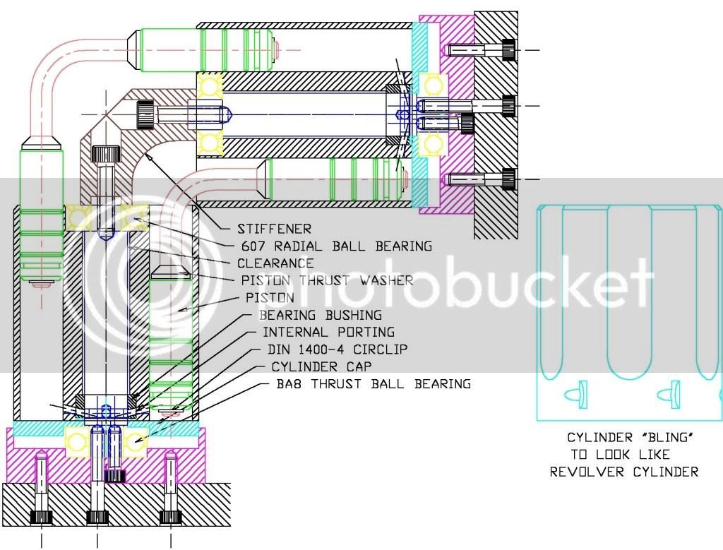
Since all the thrust will be backwards there is a thrust ball bearing - unconstained diametrically to the cylinder to prevent binding due to concentricity issues.
I have incorporated a bushing as per Captain Jerry's suggestion and a radial ball bearing at the top, the cylinder then turns on 7mm of 10 diameter shaft (3.5mm ether side of the porting for sealing), the radial bearing at the top and the thrust bearing at the bottom.

I've added a hardened thrust washer to the elbow for the piston thrust face, this will either be a push fit or locktite to the elbows.

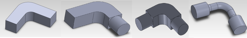
I am considering making a turning fixture for the elbows - they would still be bent from rod - but the 4mm piston running diameter would be machined in the fixture after bending to get it dead square.

I have only a rudimentary flywheel sketched in at the moment - I'm hoping to build a motor that will run without it as I want to add some "bling" features to the cylinders to make them look like a revolver cylinder.

Hence the name "Six Shooter"


Ken
 
Excellent design, Ken. I think you have all of the bases covered. The stiffener bracket is great idea. One common statement from other elbow builders seems to be the fiddly effort to get the two cylinders aligned. The bracket will either make this easier or harder. I am pulling for easier.

I can't wait to see the turning fixture that you come up with. If it works out, you will have resolved the squareness issue nicely. I hate bending stuff!

Jerry
 
I imagine that the bent shafts could be replaced by flexible shaft or not??
 
Noitoen, No - the elbows "push" the cylinders around - so flexible elbows won't work.
 
But flexible shaft like speedometer cable isn't "springy" and could do the pushing like solid shaft and would solve the perfect 90º "squareness" need.
 
Noitoen, I see what you are thinking - but the elbows do not transmit torque (A'la Bowden - speedo cable) but are rigid - each piston pushes its opposite number in the other cylinder so a Bowden cable would flex in this mode.
I do see your point however, I'll play with the idea - but I don't think it will work.

A bit of lateral thinking won't hurt though.

Thanks.

Ken
 
I'm inclined to agree with Noitoen. In fact, I think I remember seeing somewhere an elbow engine where the pistons were joined by a lap joint transected by a pin (think hinge joint). Such a joint allows the pistons to angle toward or away from each other, thus self-correcting *minor* alignments, but does not allow one piston to rotate relative to the other.

I can't think of any reason why it wouldn't work - although that may just demonstrate my poor visualization skills.
 
One place you might have a problem with Ken are the central holding bolts.

With just 3 pistons they are difficult to get to, goodness knows how bad they will be to reach when you have 6.

BTW, Stew did the 'revolver' shaping on his elbow engine.


John
 
I have given some thought to speedo type cable in the past, sheath only, no core, and the idea is good but the material is wrong. It takes a fair amount of force to bend the cable 90 degrees in a short distance and that can't be good for piston/bore friction. Maybe something lighter, like a small tension spring. A half lap joint could work, but a knife/fork joint would be better. After thinking about these solutions for too long, I realize the time could be better spent thinking about ways to be sure that all of the elbows are square and that the two shafts are co-planar. One way to solve the co-planar problem would be to make one additional elbow that fits a socket in the end of each shaft. With the valve moved to the shaft, there is no force driving the cylinder off of the shaft so there is no reason to think that it wouldn't work but Ken's bracket does the same thing and is much more rigid.

Jerry
 
Marv, Captain, the knife / fork joint makes a lot of sense but doesn't sit well with my stiffener or the asthetics - but clearly helps with alignment issues. I'll keep that in the "just in case" mental folder for now.

Noitoen, I had already been considering a "springy" elbow - but I was thinking along the lines of making it from spring wire - the thinnest that might work so that alignment issues are taken up by "flex" in the elbow. I was thinking along the lines of 2mm diameter wire - but this doesn't sit well with the asthetics.

However it gives food for thought - how about I retain the internal piston shaft portion of the elbow - drill it 2mm (see attatchment) fit the piano wire elbow and silver solder it at the circlip end ? it should be far enough away not to heat damage the temper of the bend ?

John, yup the bolts are a problem in that it uses two in close proximity - one goes through the seat and the other through the seat and the base - this makes the assembly arkward but not impossible - I think (hope) that I have thought this through - I have the assembly planned out in my head.

I'm also thinking that if I use "O" rings on the non-rotating pistons, I can get away with some clearance which will help the alignment problem which is likely to be severe with a close running fit piston - hopefully not wishful thinking.

I can always abandon three of the six cylinders if it all gets too pear shaped (put fake "bullets" into the redundant holes).

So I'm already thinking of whatever plan "B" might be required.

I vaguely remember the term six-shooter was used before so kudos to Stew. I did a search but came up bupkis.

I have also designed a reversing throttle valve to go with this as part of either the base or vertical (it doesn't really affect the design at this stage).

Thanks for the input - it is all appreciated.

Regards,
Ken


Springbend.jpg
 
Ken,

The pistons don't just go in and out, they rotate slightly as well.

When you have run the engine a while, you will see a 'herringbone' pattern on the piston sides.

In all honesty, I don't think you will be able to seal it up completely. I got my running gap under the cylinders to about 0.002", any tighter and it just locked up solid, purely because you can't get rid of all flex in the central bolts, even with shoulders on the bottom.
I spent many hours playing about with the gap and different central bolts, all to no avail, it still managed to throw a stripe of oil onto the back of a chaps jacket when I was displaying at a show, I didn't tell him BTW.


John
 
John, I bet his wife wanted to know - oops.

I'm hoping the 10mm diameter pistons will rotate on the 4mm diameter elbow ends - so they will remain rotationally static with respect to the cylinders - the "O" rings will then not rotate in the bore (high friction) and the piston is then a straight in and out function.

They will tend to rotate irregularly which will hopefully eliminate the herringbone pattern associated with the regular locus of motion within the bores.

With this design the cylinders can float and it won't affect the leakage at all.

The only leakage will come from the shaft / distributor porting (bush to shaft clearance) and the piston to elbow clearance which should be low given the small clearance and length.
Captain Jerry has also suggested "O" ring seals on the axle this would eliminnate all leaks bar the inlet to exhaust bypass past the anulus interrupt - and that goes out the exhaust - not your shirt.

I don't like using "O" rings for rotary seals - on anything but really slow speeds they tend to burn / fail because there is no lubrication mechanism.

In writing this I just remembered I have some suitably sized seals - so maybe I'll incorporate something - the worst that can happen is I'll have to junk them.

All this is of course hopefull / theoretical - the proof of the pudding however.......

Regards,
Ken
 
Bogstandard said:
Ken,

The pistons don't just go in and out, they rotate slightly as well.

They don't rotate slightly, they do 360º. They function as a crank to rotate the barrel.
 
Noitoen - correct the pistons rotate in the cylinder 1 rev per rev - where the elbow and piston(s) are solid units.
In my design they will rotate on the elbows - remaining stationary from the viewpoint of the cylinder.

I'm still waiting for someone to tell me why that won't work ?

Ken
 
Ken I said:
Noitoen - correct the pistons rotate in the cylinder 1 rev per rev - where the elbow and piston(s) are solid units.
In my design they will rotate on the elbows - remaining stationary from the viewpoint of the cylinder.

Ken

Isn't it the barrel that rotates around the piston in the solid piston/elbow design?

Other than an additional point of friction and fiddly machine work, the rotating piston scheme should work.

Robert
 
Just throwing an idea out, couldn't you mill perfectly 90* elbows out of flat stock, then attach to a face plate to turn the piston diameters. Then with a radius tool, rotary table and some creative fixturing mill it to look like a rod? Im still quite an amateur so no idea how practical this would be. Ill add some pictures to explain if that wasnt clear.

edit: heres the pic, though im sure you get it
all.png
 
Foozer - I'm talking relatively here - the cylinder rotates and the pistons go up / down / in / out but don't actually rotate relative to your viewpoint - but from the cylinder's viewpoint they rotate within each cylinder.

By having them rotate on a smaller diameter, I reduce friction losses. Also if I use an "O" ring to seal the piston - its relative motion to the cylinder is in and out only - rotation on "O" rings not a good idea (obviously if I don't seal the piston this additional bearing merely creates a new leakage path which would be worse).

The torsional friction on the elbow will cause the piston to turn slowly which will hopefully even out the wear patterns.

I was just adding seals to the design when my system decide to crap out on me and I've just lost about an hours work - dammit when its going well you forget to save - my own silly fault.

Jor2daje, that is one possible way I've also been considering - in fact I've even drawn some tooling - but I think I'm going to try the spring wire - its different and offers some simple possibilities and possible advantages.

Ken
 
You could make the pistons out of PTFE and solve the sealing problem. :hDe:
 
Ken I said:
Foozer - I'm talking relatively here - the cylinder rotates and the pistons go up / down / in / out but don't actually rotate relative to your viewpoint - but from the cylinder's viewpoint they rotate within each cylinder.
<snip>
The torsional friction on the elbow will cause the piston to turn slowly which will hopefully even out the wear patterns.

I was just adding seals to the design when my system decide to crap out on me and I've just lost about an hours work - dammit when its going well you forget to save - my own silly fault.


Ken

Guess it is from observational point. From the barrels center, then viewing the piston as the barrel does a 360. I will see the full 360 of the piston so it doesn't rotate. Semantics.

The wear pattern would probably polish/burnish itself out should one of these engines be left running more than a minute or two. Always figured that the start up wear pattern being even over the part meant a good fit :)

Robert

 
Ken

What are you planning to use for bore diameter?
 
Back
Top