Six Shooter Elbow Engine

Home Model Engine Machinist Forum

Help Support Home Model Engine Machinist Forum:

This site may earn a commission from merchant affiliate links, including eBay, Amazon, and others.
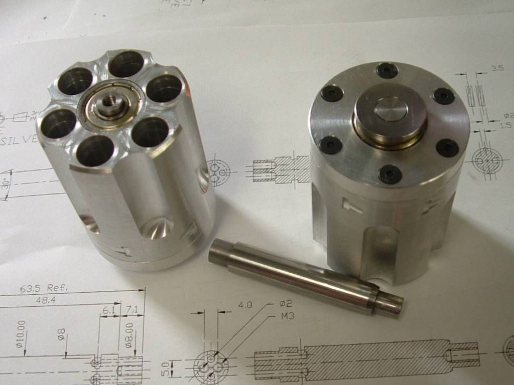
Captain, its 10mm bore by 30mm stroke (the PCD).

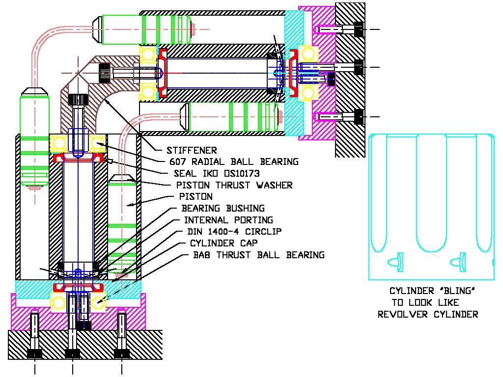
Here's the design as I'm probably going to build it.

I have incorporated seals for the axle and "O" ring grooves for the pistons. I'll build it without the seals initially to get everything sorted out first - then we'll see if the engine can handle the friction of all those seals.

If it all works the only places it can leak is out the exhaust (anulus interrupt bypass) and up the 4mm diameter x 30mm long "bearing" portion of the elbow that the piston turns on - this should be very little and lube sealed.

The axle seal is not a pressure seal but should handle 100 psi easilly enough (I once in an act of wishfull thinking subjected one of these to 2000 psi - it failed after a couple of hours use - I expected it would turn inside out instantly).

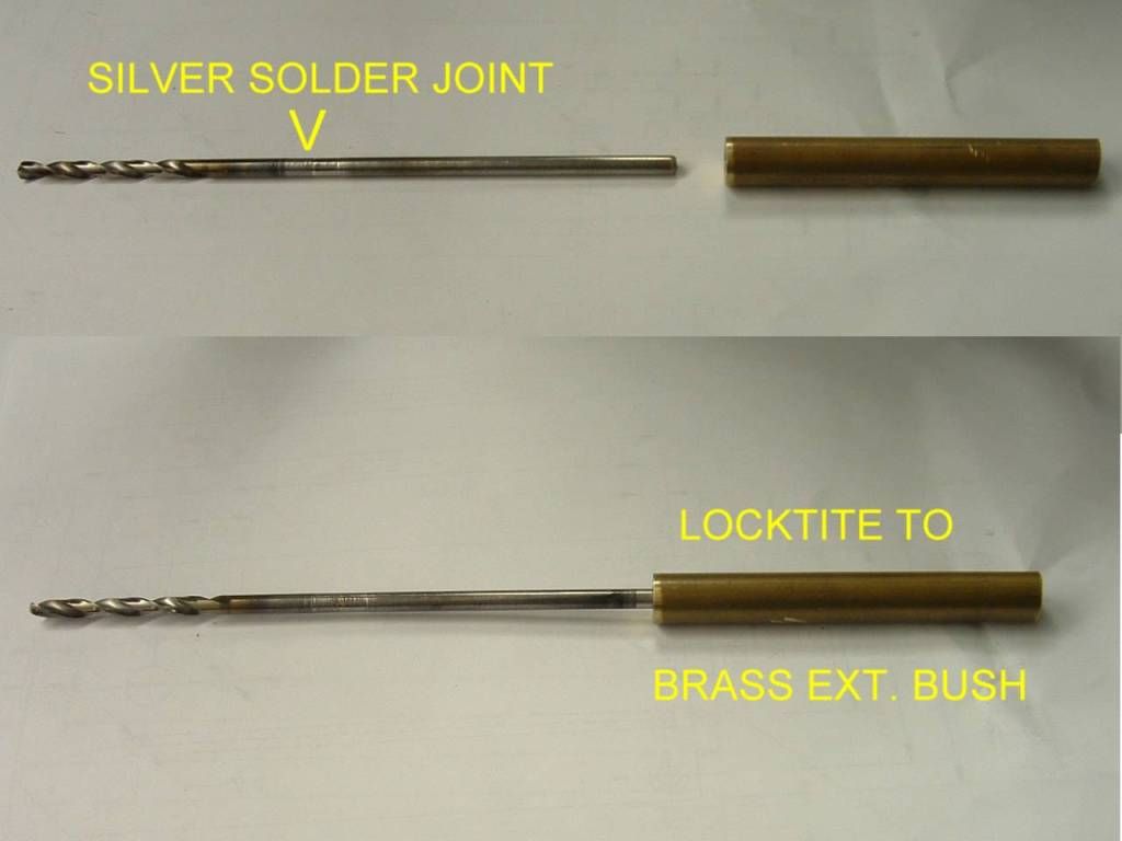
I'm going to go with 2mm spring steel elbows silver soldered into the piston "axles" - I'll be making a jig to hold both axles in the correct position during soldering - so with a bit of luck they should come out spot on - the flex and torsion in the spring steel wire should be more than ample to drive the motor but light enough to accomodate any errors without undue side loading friction.

Noitoen - if that doesn't work I'll definately try PTFE pistons.

Elbow6b.jpg


O.K. - After getting the self-propelled gearwheel out of the way, I can finally get stuck in to the elbow engine.

I have tried to design around some of the problems inherrant to the engine - leaks in particular as outlined above.

I machined the bores of the "6 Gun" barrels by spotting, drilling, boring and reaming on the RT.

I have learned not to trust drill and ream for accuracy and in such circumstances as will permit I prefer to bore before reaming - to get rid of runout errors.

firstmc.jpg


Note the split adaptor bush in the boring head - the hole in this is deliberately at 1/2° skew so I don't need to worry about clearance or rubbing on the boring bar.

Note also I have mounted the cylinders on a sacrifical piece of 16mm MDF - I miked it up to be sure it was parralell and clocked after tightening to ensure it did not compress unevenly - it worked - having said that a piece of aluminium would have been a better idea - I needed something to drill through into.

I have a location pin setup for the RT but for really accurate work I prefer a dial gauge and a mallet to get it as true as possible. I'm just a caveman at heart.

I machined both cylinders with the same set up to get them the same.

After machining I was able to mount both barrels on 3 x 10mm groundbar rods an can pass a piece down and through the other barrels (I don't have 6 pieces to hand) - this demonstrates the bores and pcd's all line up and are paralell - a great result.

I would like to tell you this is true for all 6 positions - which it should be if spot on - however one positon is great, 4 are slightly tight and one is very tight - I only need one and will mark these for the matching cylinders on assembly.

More in due course.

Ken
 
If I may offer my piston bending/making advice. Mine were made from drill rod.

As you realize, its tough because the piston has to be square in two planes. When I did mine, I decided to make a jig to bend them. I put the set screws above centerline to clamp that one side against the inside and toward the bottom of its groove, then I heated with a torch and bent it against the other edge.

DSCF0079.JPG


I did this for two pistons and they turned out dang near perfect. Just a couple thousanths off. very easy to fix with a test indicator, a dead blow and a milling vise.

The third piston broke during bending. Soooooo I clamped the other piece to the opposite side and oxy-acetylene welded the joint......This piston was PERFECT. Not even .001 off, in either plane

If I were to do it all over again, I would make that jig again with clamping segments on each side, and make each piston in two pieces, welded together...As long as your mills x and y are on par, it has to end up with a perfect square piston.

Regards,
Eric
 
Rustyknife - I followed your thread at the time - that will be my plan "B". Thanks.

Next I made a jig to mount the cylinders on for a bunch of second op work.

jigeb6a.jpg


A pair of tube dowels for location - the 14° angle is for a later operation for the timing holes - not really necessary but this chunk of aluminium already had a 15° angle on it.

This might seem like a lot of trouble but I intend to get a lot of mileage out of it and it helps with headroom on the minimill.

Drilled & tapped all the base holes in one set-up simply by moving from cylinder bore to bore.

jigeb6b.jpg


Then I fitted the end cap and spotted one hole - secured with a c/sunk cap and continued from there the same way.

jigeb6c.jpg


Cylinder c/w bases.

eb6cyls.jpg


Next step - bearing bushings, timing holes and "bling".

A question regarding the "bling" - the revolver location groove on a regular revolver is actually off-centre to the chambers - I have designed it on centre as I think this might otherwise look odd - but then some purists will be certain to tell me I should have placed it off-centre.

What's your opinion ? on-centre or off-centre ?

May I wish everyone at HMEM a happy, prosperous & accurate new year.

Ken
 
The purists who might complain, have never built an elbow engine. You should make it exactly as you would want it.

Its looking great so far.

I can't wait to see the air ports drilled
 
Next job push in the bearing / timing bushes and drill the timing holes.

More tooling :-
eb6db.jpg


A drilling bush and a specially modified cap screw.

The screw also doubled to press in the bronze bush :-

eb6pfit.jpg


There is no way to start the drill at 14° without having it wander all over the place so a mild steel bush with a matching 14° slope allows the drill to start square - for the first drilling the bush is clamped in place (in order to drill the bush) - thereafter you only need to hold it with your thumb just to get the drill started - once the hole has started there is no need for the bush which just gets in the way of swarf clearance.

eb6tim.jpg


Bottom right shows the cylinder with all the timing holes drilled through.

Now for the bling - but I have to first make a Woodruff style cutter - I also discovered why the location notch is off-centre on a real six shooter - it gives you a bit more "meat" - my original design broke through into the cylinder - fortunately I spotted the error before wrecking what I have done thus far.

Ken
 
All the following effort is for "Bling" non-functional - appearance only.

The milling fixture very useful for all this.
eb6flutes.jpg

Milling the flutes with a 12 dia. ballnose cutter.

Then I had to make a cutter out of drill rod to mill the detent grooves.

eb6cutter.jpg


The fixture should really have been square for this (it's at 14°) but that would have been more work and this is only for appearances - still it does give the repeatability.

The finished cylinders :-

eb6cylf.jpg


These were a lot of work - I've yet to decide what to make next - probably the axle or base mounting.

Ken
 
I found I needed to assemble the seals and bearings into the cylinder to determine the final shaft lengths (can't trust my own drawings) - this turned into a lot of fiddly work as the bores were all too tight and had to be meticulously mounted on the 4 jaw - a PITB when you have to spend a day to get back to were you thought you were yesterday. Ah Well.

eb6cylx.jpg


Now for the distributor shafts and the porting in the bases.

Ken

 
Got the ported bases done without breaking any drills at the intersecting holes. I got lucky when a drill became swarf bound (stupid) and jammed but fortunately spun in the chuck rather than snapping off. Lesson - clear swarf more frequently.

Not a lot of wiggle room as the holes have as little as 0.5mm clearance to surfaces or ajacent holes.

eb6cbase.jpg


I did the up side first, then stood the RT on end and rotated 90° to drill the cross holes - put the RT back flat and turned over the part using the cross holes to realign. More time spent setting up the RT and alignment than actual machining time.

Next the distributor axles and main plates.

I see a lot of people looking in but very few comments ?

Ken
 
Hi Ken

I have been following your build from the start. I am just a novice in model engine building so I enjoy to see how people do things. Keep it up.

Vince
 
Ken

I have been watching from the start. Your plan is clear and your goal is noble. The hopes and fears of future elbow benders are on your shoulder. I have a piece of cast iron bar set aside for pistons and bushings waiting for the completion of this project before I start mine. Most modifications of this design have just been cosmetic but your design is revolutionary.

After every engine build that I have completed, I have a list of things that I should have done differently or wish I had done so I'm waiting for your recap.

Jerry
 
I see a lot of people looking in but very few comments ?

Even though I got my elbow engine out of my system a fair while ago, in fact it was the first elbow build to be shown on here, I am still avidly following your build, even though not commenting much.

BTW, no jigging for mine, I bent my pistons by holding each end in a bit of pipe and holding the waisted bit in the flame and just bent it while still being heated. I had no troubles with them cracking or twisting, I just had to square them up to perfection when things were almost ready to go. It still runs to perfection today even though it has many display hours on it.

John
 
Thanks guys - as the comedians say - I know you're out there - I can hear you breathing.

When there is no response it makes you wonder if you are just boring the ears off everyone and should desist.

Just finished deep drilling 4mm dia x 123.5 deep (gallery holes in the frame plates) with a jobber drill silver soldered onto a shank, I'll post on it tomorrowish when I've finished the bits.

Ken
 
Ken

Your right. There are a lot of us out here watching with open eyes, mesmerized by what you are doing and just not quite sure what to say but enjoying every minute of it. Keep up the great work Ken.
:bow: :bow:

Cheers :)

Don
1647​
 
Yes, I'm still breathing. Or is it panting and drooling. I can't type because I have shorted out our keyboard.

The "cool factor" of this build is way over the top. Not to mention the percision of engineering and skill that is bringing this to a reality.

 
Next job should really be the distributor axles but instead I decided to do the main plates as the deep drilling has been bothering me. 4mm diameter by 123.5mm deep is "deep".

I don't have enough headroom on the minimill so the vice is out. I don't have a square either - eureka moment - my RT base makes a nice square - so I added another pair of M8 holes to the base end and used it to clamp the part vertically.
eb6mtend.jpg


The DTI is my shepherd etc. etc. - don't take anything for granted - it wasn't square.

So much so I removed the tramming dowel and adjusted the head - in retrospect a little madness methinks - this hobby will do that to you - 20 divisions on a 2 micron DTI may look like a lot but is in fact only 0.0016" (0.04mm) runout down a 140mm length for a drilled hole ??? unneccesary. Still an'all errors have a habit of stacking up against you so precision never hurts but it can be unneccearilly time consuming.

I didn't have a long series 4mm drill so I made one by silver soldering on an extension piece. I used 4mm drill rod - something smaller would have been better. So I was fussy about clocking it up in the 4 jaw - first drilled the extension piece and then turned the shank of the drill to a push fit - pushed it on using the tailstock but leaving a small gap which I silver soldered - returned to the 4 jaw for a cleanup.

The long series drill :-

eb6longdr.jpg


I've made long drills like this many times - don't worry about the absence of flutes - it makes little difference as a jobber length drill will become swarf bound long before you've used up the fluted length and you have to start peck drilling - in this case I went 1mm per "peck"

Started with conventional spot drill and drill prior to using the long series.

Still running out of headroom I had to remove my flourescent light and vertical stop and then finally the drill chuck had to go and I made a further adaptor bush for the drill to mount it into the bore of my flycutter - this time I locktited the drill into the bush so I can heat it off later - it did the job just fine.

Just to put this in perspective here's the tool up and down.

eb6dudd.jpg


Next the through holes - I mounted the part on the RT simply because it make the logitudinal alignment a doddle.

eb6rtflat.jpg


When I drilled the cross holes at the end of the deep drilling, three of the four lined up spot on and the one had wandered by about 0.2mm - WTH its only an air gallery - but it shows that deep drilling can wander - generally related to a poor start.

Just a few more holes - then the distributor axles and stiffener for a trial assembly.

Ken
 
Good progress there Ken :) - I like your angle plate Thm:

Kind regards, Arnold
 
Using the base of the rotary table as an angle plate was very creative. I am finding that half the challenge in machining is figuring how to hold the work piece. Especially when a specific tool is not readily availible.

I needed to cut facets in the cylinder for a wobbler. I was about to give up on the idea when the answer hit me. Mount a V-block sideways in the vice, a close fitting rod in the bore... (long story/short) it looked crazy, but worked.

Keep it coming
 
Made a start on the the distributor axles but ended up wrecking my first part on this build.
eb6shafta.jpg


The axle in the foreground is very precisely 2.00mm short due to an error in my drawings - creative use of expletives is somehow mollifying.

Wasn't a dead loss as I was able to use it as a comparative measure to get the next two correct - I also discovered I needed the lead-in in order to assemble through the seals without damaging them.

In spite of the seal friction the assemblies turn easilly enough and very smoothly - I can rotate them with an air gun.

Now I have to set them up on the RT to do the porting and mounting holes plus the interrupted annulus for the inlet and exhaust.

Ken

 
Ken, blame the short part on the heat wave - it was the correct length initially, it just shrunk in the cooler afternoon temperatures ;)
creative use of expletives is somehow mollifying
;D DAMHIKT, but a libation of Namibia's finest should add to the mollifying effect. Unfortunately that does preclude any further shop for the day...

Kind regards, Arnold
 

Latest posts

Back
Top