Setting work at precise angles

Home Model Engine Machinist Forum

Help Support Home Model Engine Machinist Forum:

This site may earn a commission from merchant affiliate links, including eBay, Amazon, and others.

James A. Lee

Member
Joined
Jan 17, 2009
Messages
10
Reaction score
0
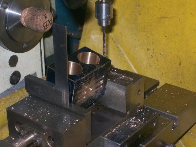
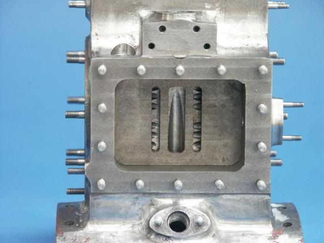
I have a question regarding setting up work in the milling vise to ensure drilling and/or milling angled engine ports to very close limits, using a dial indicator. and some simple trig. I asked this question of one of the frequent contributors to this forum and got no response, so I guess this must be one of those stupid questions. I'll accept the label, but would greatly appreciate getting a detailed answer.

Many thanks in advance.
Jim
 
Jim,
The way I have always done this is to either use an angle vise or angle plates. I always kind of hold my breath doing the first one of a set and hope for breakthrough at the right place. I always measure the distance to drill breakthrough so I get no surprises. To date I have done about a dozen steam engines this way without a failure.

I'm not sure I could do it using a DI and trig. Maybe someone could chime in on that.

Cheers,
Phil
 
Jim,
I'm quite surprised that nobody gave you answer, or at least pointed you to someone who could.

There are several methods to set an angle, each having it's own merits and shortfalls.

The simplest is just a basic swing arm protractor. Lock the arm to the angle you want, set the base on a vise jaw or vise floor and the arm on the work. Limited to whole degrees, accuracy from just a few to tens of minutes of arc.

A more precise method is a vernier protractor. Same method of set up but accurate to within a minute or two of arc. Can be used for fractions of a degree.

The most accurate is a sine bar. Requires precision blocks to set the angle. Can be used for fractions of a degree. Accurate to within fractions of a second of arc, depending on how many nits you want to pick. Also can be awkward to set up.

Another simple method, and one I use, is pre-made angle gauges. These can be purchased or shop made. A search of the site should find several examples of these gauges being used.

http://www.homemodelenginemachinist.com/index.php?topic=7546.msg79584#msg79584

 
James
It's more of a case of a question being smarter than our answers. Then you compounded it by pushing for us to show our ignorance with a stupid answer.... (grin)

You'll find this board will give its all to give you a correct answer.... when we have one, but no one here is required to do so. It's strictly voluntary.

Steve
 
James

This is how I drilled the ports for my loco engine.

100_0865-1.jpg


I carefully marked out the line I wanted the drill to follow on the outside of the cylinder then lined this line up with a square, worked fine for me.

Good luck

Stew
 
Over the last couple of year I have been using one of the Wixey angle boxes, as the base is magnetic it will hold onto iron/steel and for non ferrous I just stick it onto a bit of bar or a parallel. Used it on my TE cylinder which had the holes radially at the cylinder end but straight at the valve end, worked out the trig and then just set the angle gauge, as you can see the 12 holes were all on target

Cyl4.jpg


Jason
 
I asked this question of one of the frequent contributors to this forum and got no response, so I guess this must be one of those stupid questions.
This is your first post HOW did you ask the question?? The proper way to address folks here is on the open forum.
second of all it helps all of us here is you post an introduction in the welcome section. please tell us about yourself ,your shop , and your aspirations and or experiences in model engine building.
As others have said an angle plate or angle vise should work fine here . That aside if you want to use trig a sine bar or sine plate would also work. You could use a DI and trig I suppose but you would need a fairly rigid set up on the indicator and a dro on your z azis. Then it would be a case of getting a x distance in the x (or y distance in Y) plane a distance in the Z and then plunging in numbers to use the tangent function to measure your angle.
Tin
 
I suppose you could do it with a DTI. I always use a sine bar but I think you could do it this way.
Set up a bar in the vice at approximately the angle required.
Work out the sine and cosine of the angle required
Set up the DTI on the head to read vertically on the bar held in the vice (Z axis)
Traverse table distance equalling cosine of angle
DTI should show sine of angle
Example table traverse = 0.866 inches
DTI travel 0.5 inches (it won't be of course so adjust the bar and repeat until it is)
Angle equals 30 degrees.
I think that should work, I also think it is very complicated and will require lots of trial and error. I believe a home made sine bar would be quicker, simpler and for practical purposes probably more accurate.
Will check this setting this afternoon with a sine bar and 0.0001" DTI to confirm my maths.

Richard.
 
I would try this by using a sine table and angle bars, or vernier protractor, but now I wonder what accuracy I would actually have. Wondering what would the actual angle would be when checked with a DTI and trig.
One of the joys of model machining for me has been the dusting off of the High School/College trig and actually getting cozy with it after all these years. Keeps the grey cells in shape.
Now, I have to go down to the shop and find out. With CAD in the shop, it would be very quick to find the trig for an angle, and it gives me an excuse for keeping one of the old
pc's that otherwise goes to the recycling day.
By the way, your question was just fine. Keep asking, it helps all of the perpetual beginners (me).
 
Jim,
We had a thread on sine bars. Here is a link to it. It covers the use and making home made ones. Several other angle setting methods a also shown.

Sine bars are so easy to make an use that everyone should have one that is suitable for their machines.

http://www.homemodelenginemachinist.com/index.php?topic=2585.0

Gail in NM
 
To endorse Jasonb's post (if it needs it with such a good example) a Wixey digital angle gauge works for me. In fact it has become a must have in the workshop for all types of application from measurement to alignment.

Regards

John
 
If you're angling work in a milling vise, you really want it supported from below so that the machining forces can't move the part at an inopportune moment. DAMHIKT. This means using angle blocks or a sine bar to set the angle.

Lots of folks think sine bars are only for the metrology lab and need to be used with gage blocks. Buy or make a sine bar for use in the vise and set it with an adjustable parallel. If you read my error analysis in the thread that Gail referenced you'll see that better-than-you-need accuracy is possible without expensive gage blocks.
 
When I drilled the passages for ETW's "Unicorn" engine I used a trick out of an old Model Engineer magazine. I bent a piece of stiff wire into an L shape and put it in the milling machine's drill chuck. Then I used the point of the sticking-out leg of the L to probe alternately first the passage entry point and then the passage exit point, adjusting the angle of the cylinder block until the mill's "X" position was the same for both entry and exit points.

The original ME idea involved building a stand with two adjustable-height horizontal rods of the same length so the entry and exit points could be checked simultaneously, but you can do it with one; you just have to crank the knee up and down a lot to check first one, then the other.
 
Mainer said:
When I drilled the passages for ETW's "Unicorn" engine I used a trick out of an old Model Engineer magazine. I bent a piece of stiff wire into an L shape and put it in the milling machine's drill chuck. Then I used the point of the sticking-out leg of the L to probe alternately first the passage entry point and then the passage exit point, adjusting the angle of the cylinder block until the mill's "X" position was the same for both entry and exit points.

The original ME idea involved building a stand with two adjustable-height horizontal rods of the same length so the entry and exit points could be checked simultaneously, but you can do it with one; you just have to crank the knee up and down a lot to check first one, then the other.

Surely it would be simpler to make a scale drawing of the cylinder and use trigonometry to calculate the required angle?
 
FLYWHL2.jpg


Here is a tool I made in the shop a long time ago just for a practice piece on the new N/C machine they got for the shop.
It works pretty good for quickly setting any angle. Just put pins in appropriate holes set a parallel across them and you have your angle.
I use it a lot to quickly set up an angle if it needs to be accurate otherwise I use an adjustable protractor. :D
 
Please clarify the procedure. Assuming you are going to use a sine bar, you put the sine bar on the vise base, put the work on top of the sine bar, clamp the work by using the vise jaws, remove the bar, and go to work.
Or in the case of a sine table on the mill, would you clamp the sine table to the mill table, with the work piece bolted to the sine table. Is this basically how you do it?
 
In my shop the sine bar stays in place under the work to provide support to resist the cutting forces that might move an unsupported part held only by the vise jaws. The sine bar angle is set by an adjustable parallel or a slug of metal turned to the correct length on the lathe. A vise stop captures the sine bar and prevents it "squirting out" from under the part due to any downward pressure on the workpiece.

Note that only my cheap "beater" sine bars are used in this way. The good one used for precision taper measurement, etc. never touches the mill.

Probably 90% of the angle work I do can be handled quite nicely with a set of angle blocks, e.g. ...

http://www.use-enco.com/CGI/INSRIT?PMAKA=630-4260&PMPXNO=949269&PARTPG=INLMK3

but the sine bar is essential when you need to match odd ball angles not covered by the (generally integer degrees) angle blocks.


Latest posts

Back
Top