Rotary tables - how often are they actually used?

Home Model Engine Machinist Forum

Help Support Home Model Engine Machinist Forum:

This site may earn a commission from merchant affiliate links, including eBay, Amazon, and others.
Many years ago I made a small non geared rotary table to a George Thomas design, and of all the tools I have made this is the most used. Any job with an external radius and out it comes.
Hugh
 
Hi Nemoc,
You make very good looking flywheels. The next slide valve engine I build will have solid one piece wheel with multi spokes.
You have lit the path to good looking flywheels.
 
Many years ago I made a small non geared rotary table to a George Thomas design, and of all the tools I have made this is the most used. Any job with an external radius and out it comes.
Hugh

I have made up the same but the geared version( Hemingwaykits) - and enjoyed the tool.
again, I have something similar on the Clarkson tool and cutter grinder radius attachment and on the home made Quorn tool and cutter grinder.
 
Hi Craig,

Forgotten how to post new threads.Please give some pointers.

Now working a Quick Change Tool Post. Upgrading from the existing DIY Tool Post.

ABout to go fishing.Good weather window.

Thanks.
 
if anyone is confused about the vernier scale on their rt there is a detailed description at grizzly.com/manuals/h7527-m.pdf
 
I thought I'd throw my 2p worth in with an example of adapting and extending the tools at hand (in this case my rotary table) to do more than it was intended to do on a one-off job.

The task: The slots in the main axleboxes (bearing boxes) of most miniature locomotives call for a slight radius in the sides or "cheeks" of the boxe slots so that when sprung axles rise and fall unequally the boxes won't bind against the frame or the horn slots. Each axlebox has four radiused cheeks. For my project I needed a radius of 10.5" but having only a 9.25" rotary table (giving a max 4.625" radius work surface) an extension of some kind was required to give the 10.5" radius plus several inches to provide a working surface.

The old-school model engineering technique (and I am old school) has been to attach a plate to the rotary table, thus artificially extending its capacity, and clamp things to that, keeping in mind the rigidity will be a concern. I happen to have on hand a clean piece of scrap 3/4" steel plate (1/2" would do) which I used for the extension plate. This was drilled and bolted up and then a seat was precisely milled (notched) to receive a steel block to act as a "jaw". This jaw was located so that when the boxes were clamped in, and a pre-determined dial reading was arrived at, the crown of the radius would be located exactly as required. I simply rotated each box four times, cranked the cutter back and forth through an arc until I reached said dial reading, and wallah!

All of this was indicated in to assure that the radii were centered in their axleboxes and this setup will be used again in the future when it comes time to mill the expansion links and die blocks for the Walscheart valve gear.

AXLEBOX4.jpg
 
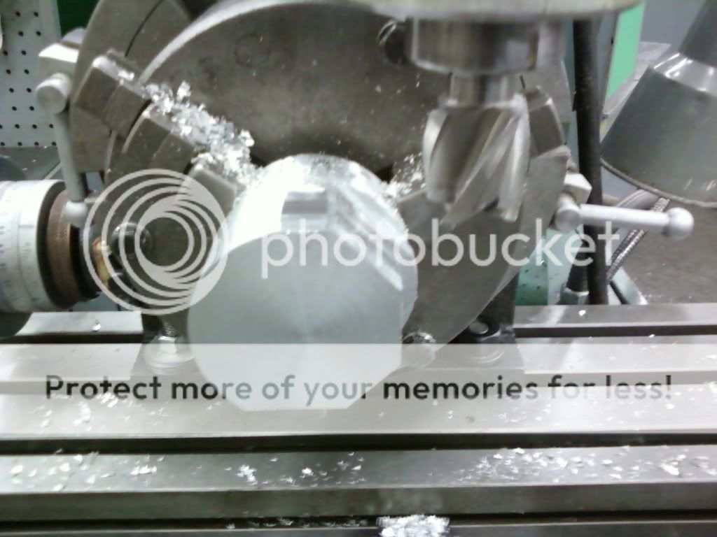
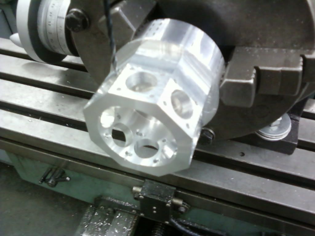
Might have missed it if it was already posted, but another use for a rotary table is to make the crank cases for any number of cylinder RADIAL ENGINES.

Here's how I made the prototype crank case for my 8 cyl radial engine I'm taking forever to make:

2a0f9a28.jpg

b6f07eb9.jpg
 
Planned to use the RT to turn the knobs for QCTP cam lock lever but would mean I have to buy a 1" brass bar.
Passed by a "Nuts & Bolts" shop and bought the Red Plastic Knobs. The Knobs seem to add color to a dull M.S.
QCTP.The red knobs cost peanuts.

IMG_1143.jpg
 

Latest posts

Back
Top