Ringbom Stirling Engine ("Tapper")

Home Model Engine Machinist Forum

Help Support Home Model Engine Machinist Forum:

This site may earn a commission from merchant affiliate links, including eBay, Amazon, and others.

Deferr

Member
Joined
May 22, 2009
Messages
22
Reaction score
2


Hello all. I am beginning my first engine build and have decided to share it with everyone on the forum. I first became interested because of my long standing interest in Stirling Engines. The decision was made to start James R. Senft's "Tapper". For those unfamiliar, it is a Ringbom style Stirling engine. The plans are featured in Senft's book shown below.

MiniatureRingbomEngines.jpg


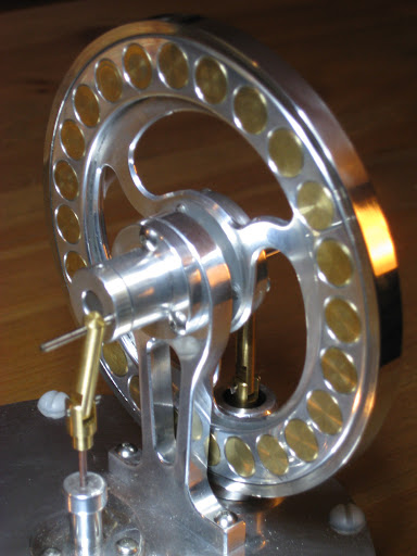
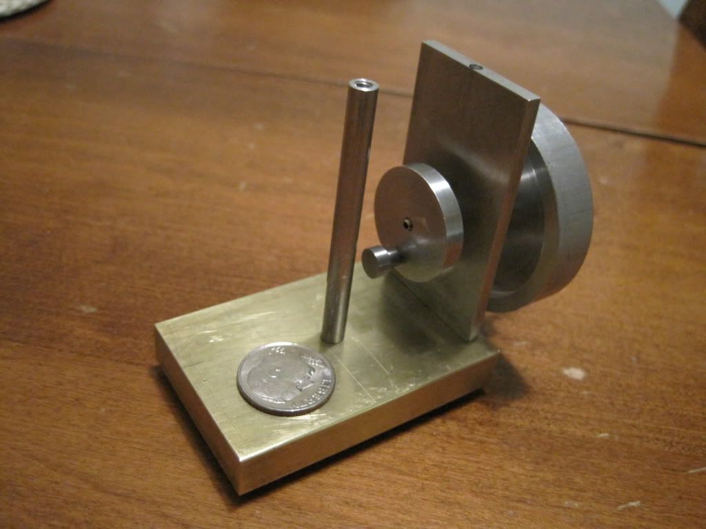
Some basics about the engine: 1.75" diameter flywheel, 1/2" piston diameter, 5/8" piston stroke, 2cc piston swept volume. I began by making the piston and cylinder. Next I made the flywheel. I have shown pictures of the parts so far.

100_2317.jpg


100_2320.jpg


Lastly, I have included a video of the testing of my piston cylinder set. I have read that it is important that the piston fall through the cylinder by it's own weight; however, when one end is sealed, the piston must be reasonably air tight. In order to test this I put a puddle of water on the counter. Next, I place the cylinder in the puddle creating an air seal. When the piston is placed in the cylinder it does not move. When the cylinder is lifted, the seal is broken and the piston falls through to the bottom.

[youtube=425,350]<object width="425" height="344"><param name="movie" value="http://www.youtube.com/v/fwStIOO33i8&hl=en_US&fs=1&"></param><param name="allowFullScreen" value="true"></param><param name="allowscriptaccess" value="always"></param><embed src="http://www.youtube.com/v/fwStIOO33i8&hl=en_US&fs=1&" type="application/x-shockwave-flash" allowscriptaccess="always" allowfullscreen="true" width="425" height="344"></embed></object>[/youtube]

Next Time: Bearing Housing, Cylinder Cap, Cylinder Retaining Ring.
 
Yeah, great start Deferr, and an ambitious project to start with but judging by your fit on piston and cylinder you shouldn't have a problem (not watched video yet).

I love this sort of unique engine. Should be a joy to watch running.

Nick
 
I was able to make some progress on the Tapper this afternoon: bearing support, cylinder cap, cylinder ring.

The bearing support was very straight forward. I chose to use flanged bearings since I had them handy. I made the overall length slightly shorter to accommodate them. The finished part is shown below.

100_2363.jpg


The cylinder ring and the cylinder cap started in the same lathe procedure with the ring being parted off the end of the cylinder cap. The hardest parts on either of these pieces were the square bore on the cylinder cap as well as getting the drill length correct. They are both shown below.

100_2368.jpg


100_2367.jpg


Lastly, I mocked up the pieces that have been constructed. This sort of mock assembly always gives me a warm fuzzy. I decided to share this pleasure below.

100_2369.jpg
 
Welcome Deferr: Your off to a nice start. I like the piston test and the video is a nice touch. I wish you the best of luck with your project. Jack B
 
I have finished the displacer rod as well as the displacer body. I will post pictures soon I promise. Here is a cool video I found of another model engineer's take on Senft's "Tapper". I'm not sure mine will be as shiny as his. I'm not much for dressing it up. I'm more mesmerized by the physics principles at work. Until next time...

[youtube=425,350]<object width="425" height="344"><param name="movie" value="http://www.youtube.com/v/u2oVJcSozM4&hl=en_US&fs=1&"></param><param name="allowFullScreen" value="true"></param><param name="allowscriptaccess" value="always"></param><embed src="http://www.youtube.com/v/u2oVJcSozM4&hl=en_US&fs=1&" type="application/x-shockwave-flash" allowscriptaccess="always" allowfullscreen="true" width="425" height="344"></embed></object>[/youtube]
 
Good progress on your build, Deferr. The piston test is a good sign!

I've seen a few of these, and always thought the nick name "Tapper" was a misnomer.
"Banger" would be more like it. You definitely know when it's running!

Best of luck!

Dean
 
I was shocked when I saw... heard the video. Much louder than I expected. Now off to the shop.
 
Brilliant isn't it! A lot of that noise is echoing though that table though.
 
I have been busy on the lathe and am finally getting around to posting my progress. Since the last picture series I have finished each component for the displacer assembly as well as the displacer rod bushing.

0102001112.jpg


I have been trying to tackle the tricky parts of this engine first. Since I have little experience in engine building or working with a lathe, many things that I expected to be hard have been easy (boring). Conversely, many things I thought were easy have been hard (making the recess in the flywheel).

My next big challenge will be internal threading of the cold end of the displacer housing. I am considering making a tap from CR steel and using is to thread the 3/4-40 threads. I will keep everyone posted and maybe try to get some action shots of the lathe at work.

Please chime in if you have suggestions or things to keep in mind as i tackle internal threading.
 
Deanofid said:
I've seen a few of these, and always thought the nick name "Tapper" was a misnomer.
"Banger" would be more like it. You definitely know when it's running!

NickG said:
Brilliant isn't it! A lot of that noise is echoing though that table though.

I am already thinking of my next engine build. Senft suggests the use of dashpots in the displacer rod. I am assuming these would limit the noise significantly as well as reduce the violent accelerations the displacer is subjected to.
 
I was sitting yesterday thinking about my progress on "Tapper" and became worried about my choice of aluminum rather than brass for the flywheel. Too little rotational inertia will almost certainly cause sporadic motion of the power piston. So..... as a true BSME I did some math.

The rotational inertia of the flywheel as designed is about 0.81 in2-lb

The rotational inertia of my aluminum version is about 0.26 in2-lb

That's only 32% of the designed value :wall:

I am debating whether to add weight along the top rim of the flywheel (solid brass inserts) or try it as is and make a change later if needed..... :shrug:

Lastly, I have finished some of the cold end and will post pictures as soon as I get a chance.
 
deferr, I too used in the past aluminium instead of brass to make flywheels, but the stirling engines are much more prone to fail I think then the steam engines that I had built

anyway, I wish you that you could solve everything and get the engine running soon
till now you have done a great work!


Deferr,
You could "shrink" a steel or brass ring over the outside of the alum flywheel.

A thought

Tony
 
Deferr said:
I am debating whether to add weight along the top rim of the flywheel (solid brass inserts) or try it as is and make a change later if needed.....

If the engine fails to run with the aluminum flywheel, you might try wrapping some turns of wire solder around the periphery of the flywheel to test the utility of a more "momentous" flywheel. I've done something similar in the past using plumber's wire solder which is about 1/8" thick. If it improves performance, then make a heavier permanent flywheel.

If you don't have any plumbing solder, heavy gage copper wire might work. Lacking both, just tape some gold Krugerrands to the rim. :)
 
mklotz said:
If the engine fails to run with the aluminum flywheel, you might try wrapping some turns of wire solder around the periphery of the flywheel to test the utility of a more "momentous" flywheel.

After some time in the shop I came to a similar conclusion. I will stick with the flywheel I have made for now. After the first test run, I will test a heavier flywheel out of curiosity (or necessity, we will see).

cobra428 said:
Deferr,
You could "shrink" a steel or brass ring over the outside of the alum flywheel.

I like this idea for a permanently heavier flywheel if necessary.

Thanks guys! I will have pictures of progress tomorrow evening I promise. Our camera doesn't work too well as of late (they don't like being dropped on the lens). We are replacing it tomorrow evening and I will share pictures.

 
Deferr,

When I tried the aluminium flywheel on mine it had too low a moment of inertia. But the stirling has 2 power strokes per rev so you might get away with it. It will fly along that's for sure!

Nick


Looking great!

As yourself and others suggested, I too added brass inserts as well as a SS ring to my Al flywheel;

stirling2.JPG


Which book are these plans from?

Thanks.


Brass inserts look great and you can take them out and tweak it as necessary - you could also use it to balance the assembly too!

Nick
 
I have done quite a bit of work on the lathe lately. Not so much on the Ringbom. I am still getting the lathe tweaked and setup as I go. I have a feeling this will be a continuous process. As for the work on the Tapper, I made the base tonight so I was able to get some more mockup shots of what the engine will look like. Now for the action shots.

First I squared the stock up and laid out where the support mounting holes were to go.
1-14-10001.jpg


Next I used my brand new 4 jaw chuck to drill the holes as laid out. Here is the setup in the lathe.
1-14-10003.jpg


So far everything fits and rotates very freely. We will see how the piston cylinder works out when I get a chance to make the top mounting plate.
1-14-10005.jpg


Latest posts

Back
Top