
You are using an out of date browser. It may not display this or other websites correctly.
You should upgrade or use an alternative browser.
You should upgrade or use an alternative browser.
Re: First Engine No Plans.
- Thread starter gbritnell
- Start date


Help Support Home Model Engine Machinist Forum:
This site may earn a commission from merchant affiliate
links, including eBay, Amazon, and others.
- Status
- Not open for further replies.
PTsideshow
Well-Known Member
- Joined
- Apr 12, 2008
- Messages
- 503
- Reaction score
- 19
PTsideshow
Well-Known Member
- Joined
- Apr 12, 2008
- Messages
- 503
- Reaction score
- 19
Machining instructions for engineering plastics
Adhesive bonding instructions for engineering plastics
Plastic Brochures
Machining guide for Quadrant engineering plastics
Three of the great downloads from this site!
http://www.bayplastics.co.uk/downloads.htm
Adhesive bonding instructions for engineering plastics
Plastic Brochures
Machining guide for Quadrant engineering plastics
Three of the great downloads from this site!
http://www.bayplastics.co.uk/downloads.htm
PTsideshow
Well-Known Member
- Joined
- Apr 12, 2008
- Messages
- 503
- Reaction score
- 19
MatWeb's searchable database of material properties includes data sheets of thermoplastic and thermoset polymers such as ABS, nylon, polycarbonate, polyester, polyethylene and polypropylene; metals such as aluminum, cobalt, copper, lead, magnesium, nickel, steel, superalloys, titanium and zinc alloys; ceramics; plus semiconductors, fibers, and other engineering materials.
http://www.matweb.com/index.aspx
glen
http://www.matweb.com/index.aspx
glen
- Joined
- Feb 17, 2008
- Messages
- 2,326
- Reaction score
- 440
Since the subject of slip-sticks came up and this is the breakroom, a quick story. In my display case of family items I have two slide rules. they are both identical except for their ages. They are both bamboo K&E single sided with just the basic scales on them. The newer one was given to me by my mother when I started Physics class in high school in 1955. The older one was hers. She used it while on the design team for the North American B-25 bomber designed and built during World War II.
As the story goes, and I have no reason to doubt it, the main office building at the North American plant had a top down pecking order structure. The most senior executives and their staff were on the top floor. The next floor down had the engineers and the drafting positions which needed to be next to the engineers. As an engineers time was quite valuable during the rush of war, they offloaded the complex calculation to the computers which were on the next floor down. They would set up the equations that needed to be solved, graphed or other numerical functions applied and send them down the the next floor to the computers. I am sure that most of you are wondering what I am talking about because computers as we know them today did not exist during those years.
The computers were people with math degrees, mostly women, who solved the equations and crunched the numbers needed by the engineers and then sent the results back to the engineers. Most of them used slide rules as mechanical calculators were scarce during the war. The mechanical calculators were only used where a higher degree of precision was necessary and the slip-stick could not be used. My mother was one of these computers.
So you see it was only natural that I became involved using computers as a tool later in life. After all, MY MOTHER WAS WAS A COMPUTER. ;D
Hilmar, I made the crank from solid excepting the counter weights which are attached. I destroyed both the silver solder crank blank that came with it and the cast iron counter weights. Weights cracked when peening them on.  Made a new set from steel, worked perfectly. Ill post a pic of the pretzel, er first crank, but its on a computer sans motherboard at the moment.
Come on man, I need you to work through that problem and get back on course - there may be other nasty bits I need you show me how to made
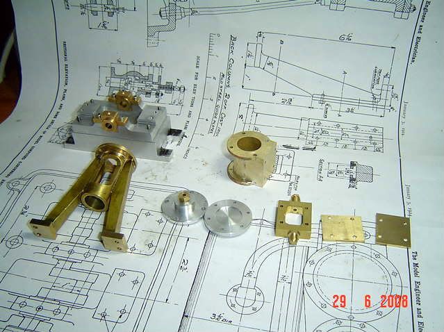
Ok progress pics. In the previous post, the pics show the oil cups I made for the main bearings, but I felt eccentric straps and big ends should also have some way of delivering oil.
Here are the little cups I made for the eccentrics, the small OD is 1/16, the six are sitting on a dime.

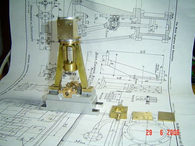
Heres a shot of them installed - its triple so there's 3 or 6 of everything!

The big ends required a bit more thought as the counter weights narrow in on the connecting rod once the bearing is cleared you can see that in the pic of the crankshaft above
So I decided to have a base, pipe and cup at the top and to twist it around to the side so it would clear the counter weight.
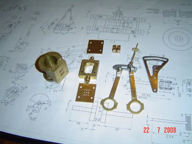
Here are the parts are being assembled. The brass tube is only .047 OD and thats #67 reamer to clean out the brass tube ID after cutting. You can see the visor magnifier in the background that gives me a fighting chance on these parts

And here they are installed Incidentally, the geometry formed by the tapered connecting rod where it meets the U shape at the top was one very challenging aspect of this engine the parts have to blend together with a radius to look right. Maybe a five axis cnc? Still would require hand work to blend it me thinks. This was a close to sculpting as my machining as ever come, tedious needle file and emery work!
The cup had to be where it is to clear the counter weights and looks somewhat like prototypical practice

More fun and games today, put engines a side and spent the day tuning up a Starrett #20 master precision squares and M&W #400 long day, now I know why the cost so much new
Made a new set from steel, worked perfectly. Ill post a pic of the pretzel, er first crank, but its on a computer sans motherboard at the moment.Come on man, I need you to work through that problem and get back on course - there may be other nasty bits I need you show me how to made
Ok progress pics. In the previous post, the pics show the oil cups I made for the main bearings, but I felt eccentric straps and big ends should also have some way of delivering oil.
Here are the little cups I made for the eccentrics, the small OD is 1/16, the six are sitting on a dime.
Heres a shot of them installed - its triple so there's 3 or 6 of everything!
The big ends required a bit more thought as the counter weights narrow in on the connecting rod once the bearing is cleared you can see that in the pic of the crankshaft above
So I decided to have a base, pipe and cup at the top and to twist it around to the side so it would clear the counter weight.
Here are the parts are being assembled. The brass tube is only .047 OD and thats #67 reamer to clean out the brass tube ID after cutting. You can see the visor magnifier in the background that gives me a fighting chance on these parts
And here they are installed Incidentally, the geometry formed by the tapered connecting rod where it meets the U shape at the top was one very challenging aspect of this engine the parts have to blend together with a radius to look right. Maybe a five axis cnc? Still would require hand work to blend it me thinks. This was a close to sculpting as my machining as ever come, tedious needle file and emery work!
The cup had to be where it is to clear the counter weights and looks somewhat like prototypical practice
More fun and games today, put engines a side and spent the day tuning up a Starrett #20 master precision squares and M&W #400 long day, now I know why the cost so much new
I think as a first step I would buy an array of small metric bolts and see which of them fit the unknown threads.
The next step, for the threads you can't identify that way, is off the top of my head, I have not tried it. If it is a viable method I'm sure I'm not the first person to have thought of it.
Selecting a bolt of the correct OD, turn off the threads down to the minor diameter, but leave most of the front thread. Your bolt becomes a bolt with one thread.
My theory is that the single thread bolt should? engage with the tapped thread without damaging it. Counting the number of turns you can screw the bolt in, and measuring the depth of engagement will give you the pitch.
here's some pics on whats available, if interested let me know. I could be strong armed into paying for the shipping in NA and have appropriate packaging from something that just arrived so no packing/shipping costs to be added provided it comes out to less than say $50 which it should be. Everything but the height gauge and mag base is quality NA, British or Japanese brands. The indicators work perfectly and the mics tests dead on with gauge blocks. The square is better than .0002" over the 6" blade, tested by me with Mitutoyo bevel edge inspection square.
PM if interested, thanks


the packaging on these looks a lot like the chinese stuff but this is RTC made in Japan


Everything but the height gauge and mag base is quality NA, British or Japanese brands. The indicators work perfectly and the mics tests dead on with gauge blocks. The square is better than .0002" over the 6" blade, tested by me with Mitutoyo bevel edge inspection square.PM if interested, thanks
the packaging on these looks a lot like the chinese stuff but this is RTC made in Japan
Tin Falcon
Well-Known Member
- Joined
- Jul 9, 2007
- Messages
- 7,207
- Reaction score
- 787
my current day job I work for a scale company. Most of the time is spent on PM, inspection calibration of scales we also do repairs installs rentals etc.. The accounts are varied, nursing homes ,flavoring plants soda companies, chemical plants ,postal /mailing houses,labs etc.
the scales range from micro balances that weight fractions of a gram to railroad scales that are in 100 lb increments.
Tin
the scales range from micro balances that weight fractions of a gram to railroad scales that are in 100 lb increments.
Tin
rickharris
Well-Known Member
- Joined
- Jan 19, 2008
- Messages
- 313
- Reaction score
- 0
http://www.pts-uk.com/index.htm offer very small sized threaded components - Bolts - Machine screws Hex heads at reasonable prices around £7 ish per 100.
They go down to M1 x 2 to M1 x 10 in various materials
Interesting!
They go down to M1 x 2 to M1 x 10 in various materials
Interesting!
- Joined
- Jan 1, 2008
- Messages
- 74
- Reaction score
- 0
Kevin , Did you find the plans on line or is that your own design? I've always thought that would be a nice setup. How is the cornering stability?
Dick
Dick
bronzecaster
Member
- Joined
- Aug 21, 2008
- Messages
- 5
- Reaction score
- 0
It's been a long time since I've posted to any board (heck since I've even joined any board) but I'm impressed with the friendliness of this one. So it's time to join in. I've been building model engines for a while, both bar stock and my own castings/designs. I've learned enough to know that I'm still a amateur machinist, but by listening to you all maybe someday that rating will change.
from southeast, MO
Chuck
Metal Mickey
Well-Known Member
- Joined
- Jul 5, 2008
- Messages
- 612
- Reaction score
- 6
bronzecaster said:It's been a long time since I've posted to any board (heck since I've even joined any board) but I'm impressed with the friendliness of this one. So it's time to join in. I've been building model engines for a while, both bar stock and my own castings/designs. I've learned enough to know that I'm still a amateur machinist, but by listening to you all maybe someday that rating will change.
from southeast, MO
Chuck
Welcome, welcome, welcome. They are a brilliat bunch and helped me no end already and I am also a novice (albeit and old one) :big:
kf2qd
Well-Known Member
- Joined
- Apr 1, 2008
- Messages
- 588
- Reaction score
- 76
Bronze bushings and oilite bushings are not the same thing. A bronze bushing is made from bronze - nothing else. An oilite bushing is made from sintured bronze and the gaps filled in with oil. A bronze bushing will take more load & speed than will an oilite bushing and will outlast is. A bronze bushing will need some lubricant for the best lifespan. a bronze bushing is relatively hard, an oilite bushing is relatively soft and will fracture much more easily than will a bronze bushing.
Hi Tony
Wow you have made a fantastic job of that, Very well done indeed.
I like the look of your Compound vice for the drill, does anyone know if they are available in the UK ?
That sure does look like it makes the job of rounding off the levers really first class.
Please ..... More pictures and when you finish A VIDEO. Pretty PLEASE( that's akin to begging i know but this engine looks so good) :bow: :bow: :bow: :bow: :bow: :bow:
Kind regards
Malcolm
Thanks John.
For such a small cost it would seem churlish not to have one.
Your new lathe looks superb (TOOL ENVY again) I am sure i don't have to ask for you to do your usual detailed and always interesting diary of it's installation and fettling, Which i am very much looking forwards to.
Kind regards
Malcolm
kf2qd
Well-Known Member
- Joined
- Apr 1, 2008
- Messages
- 588
- Reaction score
- 76
I have found that I like lower speeds on coarser threads and higher speeds on finer threads. Has a lot to do with carriage speed, Coarse thread means that the carraige moves farther per turn of the spindle. And I find thqat threading is actually easier on a large lathe as compared to a small lathe. Why? I'm not sure...
- Status
- Not open for further replies.
Similar threads
- Replies
- 10
- Views
- 3K
A