
You are using an out of date browser. It may not display this or other websites correctly.
You should upgrade or use an alternative browser.
You should upgrade or use an alternative browser.
Pile Driver
- Thread starter Brian Rupnow
- Start date


Help Support Home Model Engine Machinist Forum:
This site may earn a commission from merchant affiliate
links, including eBay, Amazon, and others.
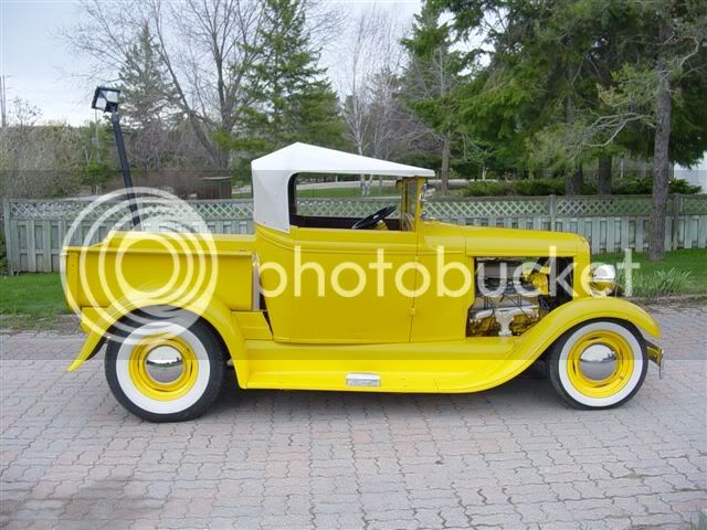
Here ya go Rayanth---I built this seven years ago. I have had almost every body style of model A over my many years in hot rodding, but never had a roadster pickup.---So---I started with an old two door sedan, cut three foot out of the back of it, cut the top off, molded the top of the doors and cab section, built the box from scratch, built the top from scratch---The cab and box are steel, the fenders and splash aprons are glass.
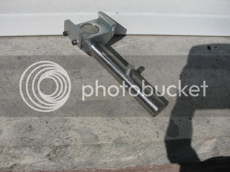
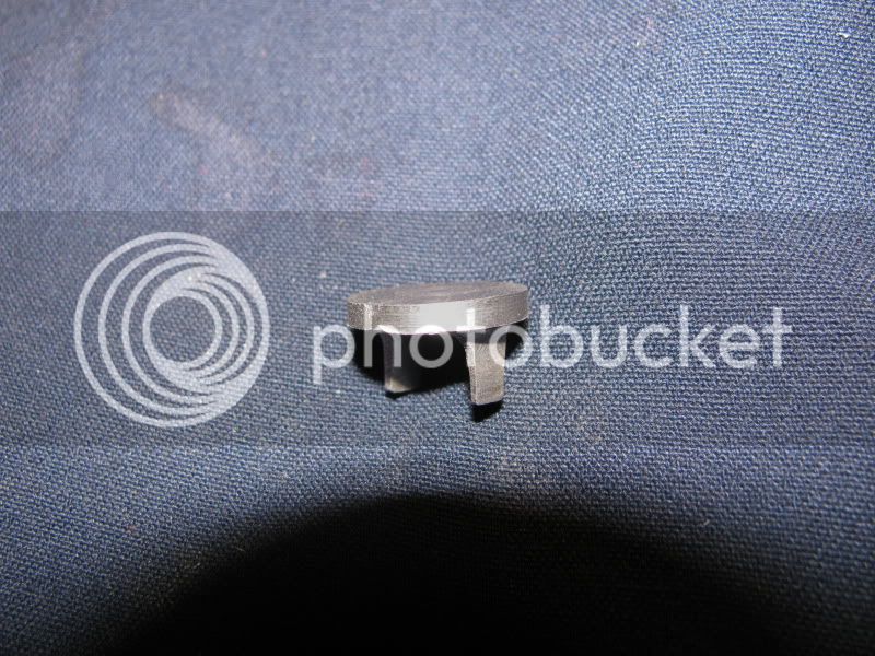
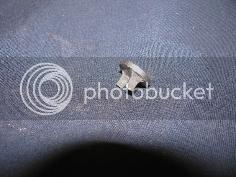
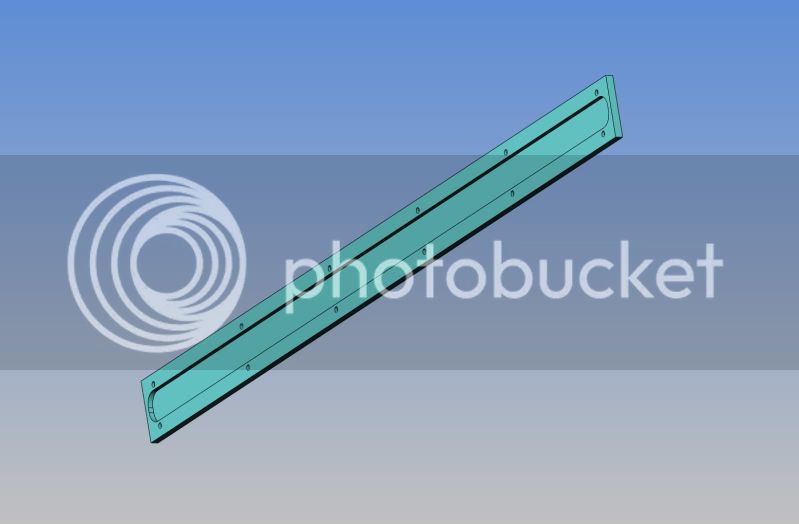
This afternoon I finished the "drop hammer" part of this pile driver. Its only four little pieces, but it seemed like a lot of work. I let it fall down the column without the magnet in it, and with the magnet in it, and didn't see any visible difference in the way it fell, nor the rate of speed. What I did see however was that the weight of the 5/8" dia. stainless rod makes the aluminum slider "cant" over because of the offset weight, and it "stutters" as it falls. I want it to fall "cleanly" each time, so I am going to insert a piece of 3/16" dia. round aluminum rod into the stainless at 90 degrees down at the bottom end to ride against the face of the brass column and keep everything "in line" as it falls.
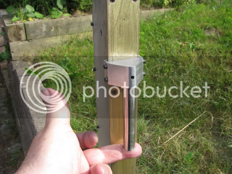
Here you can see the "Rider Pin" that I added to the side of the stainless steel "drop hammer" to keep the whole assembly from cocking sideways and binding as it slides down the brass column. You can also see the very powerfull rare earth magnet which is epoxied into the recess in the slider.
Rayanth said:It is indeed a nice looking vehicle. Not sure I would have chosen yellow....maybe metallic purple....I do love a good purple :big:
Did you check that the magnets were strong enough to raise the hammer?
- Ryan
Rayanth---I'm glad you asked that question!!! I had a peice of brass bar about 3" long left over from the main column, so I slid the drop hammer over it and stuck a second magnet against the back side of the brass bar----and one magnet DIDN'T have enough strength to lift it!!! However, two magnets stacked together seems to lift it fine. I don't have room in the casing to put double magnets on my chain links, so I deepend the counterbore in the aluminum slider and stacked two magnets in there. Noitoen had me a bit concerned with his dire warnings of eddy currents, etcetera, so I had put a 3/16" hole all the way through the slider so I could get a knock out pin thru there to remove the magnet from the slider if I needed to. I knocked out the first magnet, deepend the c'bore another 3mm, then epoxied two magnets in place. Now a single magnet on the far side of the brass bar will lift things okay. If I really have to I will run a 3/8" drill full length of the 5/8" stainless to lighten it up some. EDIT EDIT--It was still "To close a thing" so I DID drill the center out of the 5/8" stainless with a 3/8" drill, from the top end down to about 3/8" from the bottom end. Now a single magnet moving behind the brass bar will pick the hammer up every time. I wll turn a fancy little brass cap to plug the top hole.
Today I'm down to the last two parts, the magnet mounts for the roller chain. While experimenting earlier today, I have found that the magnets "attraction" power is dramatically enhanced if the magnet is backed up by a piece of mild steel, so I will be making the magnet/chain mounts from steel, not brass. I really don't care for working (at least milling) steel, as it is so much tougher than machining aluminum or brass, but in this case steel is what it will have to be. I have one mount about half made right now, but have ran out of energy for today. I see that about 1900 people have had a look at this thread, but not many have commented. I guess I understand that----after all, a pile driver is kinda "Out There" in the world of model engineering. I have had fun building this one, and as in every thing I build, I continue to learn something new each time. I really hope I can silver solder my magnet mounts to the roller chain without a lot of problems, because I am really looking foreward to seeing this run.----Brian
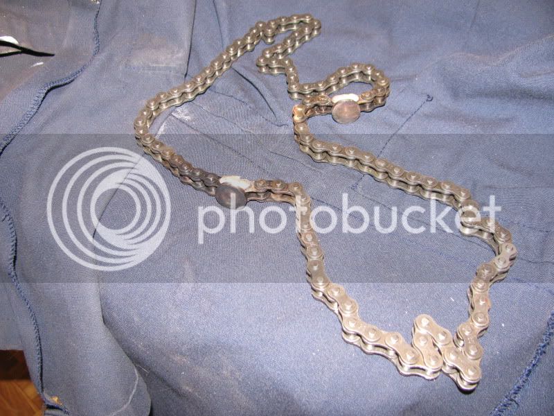
Well, here we have the first magnet mount to be silver soldered to the roller chain. Just as I suspected, nasty, miserable little buggers to machine from mild steel. One down, one to go----
Here we have the two magnet mounts finished and silver soldered to the roller chain. I'm really quite pleased with this, as I actually managed to do it without soldering 2 or 3 chain links together while doing it. Since I ended up putting two of the magnets together into the "slide hammer", and they come in packs of 3, I'm now off to Princess Auto to buy another pack of magnets because I'm short one.
Wife and I just got back from a 4 day road trip with a couple of our grandchildren. Here I am with my two beauties at "Lake on the Mountain" in Picton, Ontario. The pile driver is essentially finished except for adding 4 set screws to the drive collar on the driveshaft to engage with the "spaces" between the gear teeth on my gear reducer. I used "J-B Weld epoxy to attach the magnets to the magnet mounts on the roller chain, and its been "setting up" since I left four days ago, so I hope it will hold sufficiently. I have ran some "simulated tests" while everything is disassembled, and the magnets appear to be strong enough to draw thru the brass slider bar and move the "drop hammer" vertically up the full length of the brass slide bar. With luck, I will have a video sometime this weekend.-----Brian

Brain, love the ride, that is my favorite color match, it would and only could look better at my house, maybe not, I was in the oil field today and was telling a customer about your pile driver, he said if you charge less than us you can come drive some and also drive casing, the casing in 40' could you make a longer on, ready to see if working, nice looking grand children, they don't even looked spoiled, glad that you can enjoy them, take care, Lathe Nut
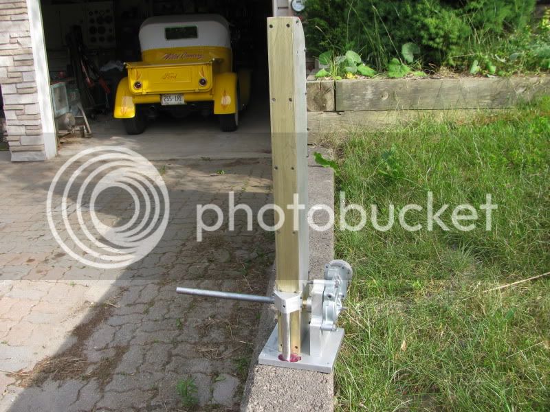
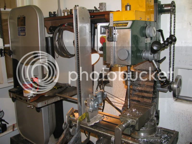
Here we have partial re-assembly, in a bit of a lash-up just to check running clearances and fits. The drive belt is a 3/32" dia. rubber o-ring. Everything appears to run very smoothly with no "sticky spots" and very little efort required to turn the mechanism. I will let it run for half an hour, powered by the milling machine, before I complete the assembly.
No Joy----No Joy!!!!--Its all back together, but there is just too much friction between the slider and the brass strip. The slide hammer kind of staggers up the column like an old drunk. Sometimes it gets to the top, sometimes it only gets part way up, sometimes it just gives a grunt and a wiggle and doesn't go up at all. The dillema----The magnets have to have really strong attraction in order to lift the weight of the slide hammer, but that same very strong attraction creates a lot of friction. So----Next step is maybe to create a set of hidden UHMW wheels---Let the bugger ROLL up the column. Sorry---No video after all.----Brian
Kel---Pretty hard to make the brass plate thinner. Its 3/16" thick now, and I have the heads of the #5-40 shcs buried in it. I could probably go to flat head capscrews, but I'm not quite ready to go there yet. Since everything else on it works so well, I will probably redesign the head of the "slide hammer" to accomodate some small wheels to cut down on the frictional drag. This whole thing is a voyage of discovery for me. Even in a worst case scenario, where it doesn't work at all, 90% of the material is salvageable for other projects. The biggest problem seems to be frictional drag, and a couple of sets of small wheels will probably fix that. I don't have a lot invested in this project time wise, so I'm not worried about making a few changes as I go along. One of my constraints is that everything on the slide hammer and the brass bar must be made from materials that are not affected by the magnets, so I'm limited to aluminum, brass, or 316 stainless. This entire project is more of a "boredom breaker" than anything. Thanks for having a look and for your suggestion.---Brian
I may have found a way to make the front slide bar thinner, where it counts.I can mill a slot 3/4" wide x 1/8" deep full length on the side facing the magnets. There is enough slack in the chain for the magnets to move out and ride in this slot. The magnets and magnet mounts are only 18mm (0.71") wide. This won't do much for the friction issue, but will greatly increase the magnetic attraction.
I have more insight into whats going on--I had made up a small brass "cap" to plug the hole in the top of the aluminum slider. This cap was made to cover the hole I had put into it when I drilled out the center of the 5/8" s.s. rod to 3/8" in order to lighten things up. When things still seemed too heavy to lift properly, I heated up the aluminum slider to get the brass cap off and drill the center hole in the 5/8" rod out even more, to 1/2" diameter. Strangely, this didn't seem to make any difference, even though the whole slider was now lighter. This morning I was playing around with my two remaining magnets which had never been installed in anything, and discovered that they seemed to have about 10 times the magnetic attraction that the magnets epoxied into the slider had?????----Suddenly a light went on---THE HEAT I HAD APPLIED TO THE SLIDER TO REMOVE THE BRASS CAP HAD DESTOYED THE MAGNETISM OF THE TWO MAGNETS EPOXIED INTO PLACE!!!! I removed the two magnets which had been epoxied into place in the slider, and replaced them with the two new magnets. now the slider rises up to the top every time with no difficulty.----More to come---
zeeprogrammer
Well-Known Member
- Joined
- Mar 14, 2009
- Messages
- 3,362
- Reaction score
- 13
I do like seeing projects of things that engines can drive.
Very enjoyable thread. Why is it posted in the Break Room? It's certainly a 'work' in progress.
Very enjoyable thread. Why is it posted in the Break Room? It's certainly a 'work' in progress.
maverick
Well-Known Member
Don't you just love those A-HAA moments. Nice project, You're a very creative guy.
Zee---It started out as an idea, and I wasn't sure I was going to build it. Then I decided I would build it, but I don't know how to move it over to a "work in progress". Perhaps a moderator could help---(Please).---Thanks for having a look Zee----Brian
Similar threads
- Replies
- 37
- Views
- 12K