Pile Driver

Home Model Engine Machinist Forum

Help Support Home Model Engine Machinist Forum:

This site may earn a commission from merchant affiliate links, including eBay, Amazon, and others.

Brian Rupnow

Design Engineer
Project of the Month Winner
Joined
May 23, 2008
Messages
14,997
Reaction score
8,295
Location
Barrie, Ontario, Canada
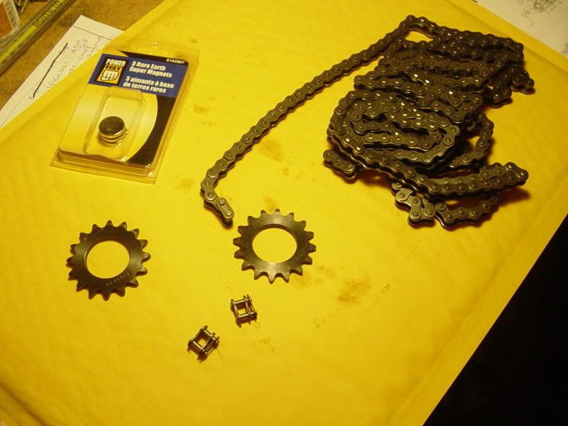
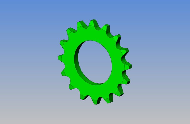
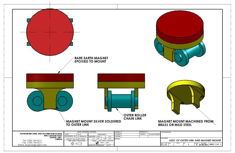
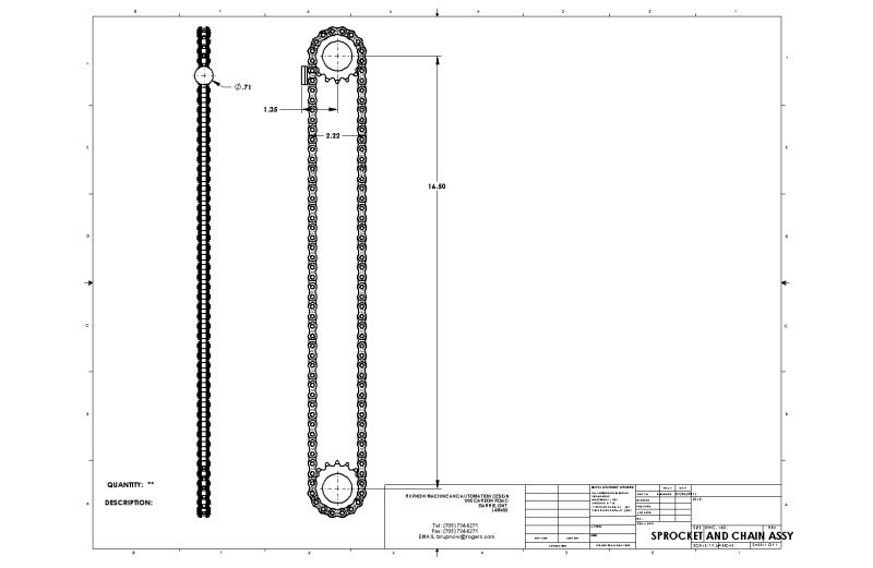
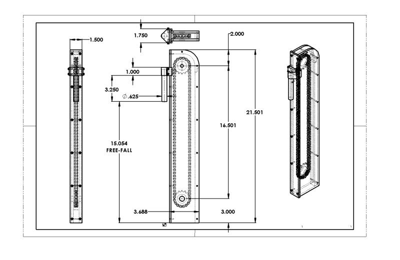
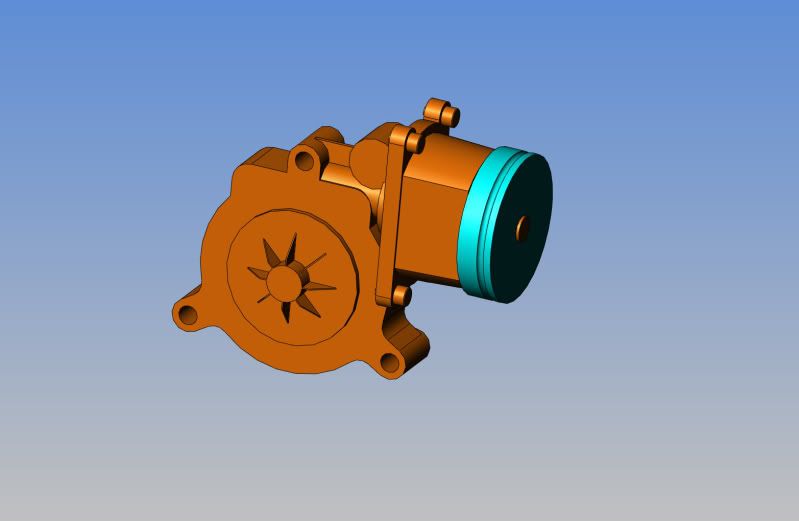
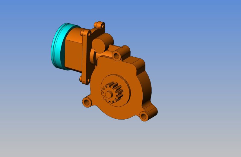
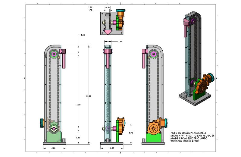
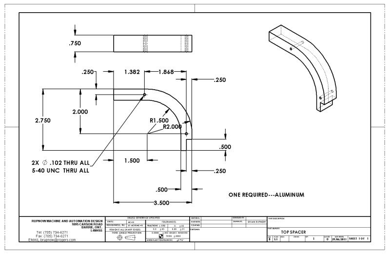
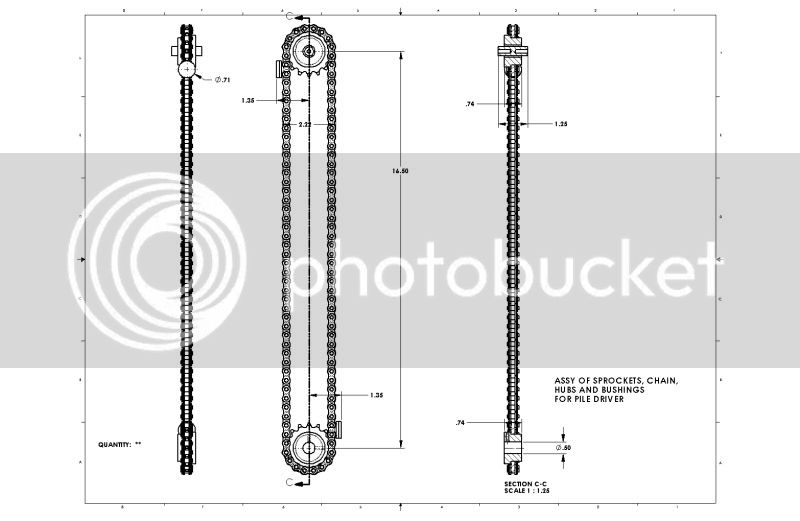
Last night I couldn't sleep. Rather than counting sheep (which doesn't work anyways) I started casting about for interesting things I could drive with some of my model engines. So far I have designed and posted the Slinky Machine, and it was a big hit. People also liked the Pumpjack oil pumping model which I designed, built, and posted.(although I haven't seen anyone else build one). Recently I built and posted the Bubble Machine, which is cute. I didn't post plans, because it was so simple that anyone could replicate it after seeing the pictures and video. Two lots down from my house they are digging the basement for a new house with a large excavator, and for half an hour I persued thoughts of building a working model of that, but gave up---Just too many motions to replicate. Then I thought ---"Hey---What about a pile driver." That one would be fairly simple. I'm thinking an aluminum column/tower with a small chain sprocket at the base and a nylon top shoe for the chain to slide around. The "sliding hammer" would be a section of mild steel rod with a nylon guide attached which slid up and down rails in one face of the column. The roller chain could have a rare earth magnet attached to it so that as the bottom sprocket rotated and the chain moved up the tower, the rare earth magnet would pull the sliding hammer to the top of the tower. Then when the chain passed over the top shoe, the magnet would be pulled away from the slide hammer and it would fall to the base of the tower on the guides, thus "driving" the piling. This motion would keep repeating itself. A small gear reduction unit would probably be needed at the bottom drive sprocket. I think this would make an interesting display and could be driven by an air, steam, or I.C. engine.---Anybody interested?----Brian
 
One refinement would be an actual pile to drive. Picture a rod that slides in a split sleeve (so the friction acting on it could be adjusted). When the hammer drives the pile far enough down into the base its bottom end triggers a lever mechanism that pushes it back up so the action can repeat.
 
mklotz said:
One refinement would be an actual pile to drive. Picture a rod that slides in a split sleeve (so the friction acting on it could be adjusted). When the hammer drives the pile far enough down into the base its bottom end triggers a lever mechanism that pushes it back up so the action can repeat.

Maybe a "pile" with a bit of spring under the bottom to return it to position zero aftr each impact. Otherwise, too difficult to accomplish.
 
Nice idea Brian...and certainly something different. When I first saw the subject line though, I thought maybe you we adapting the recent discussion on the air nailer to a pile driver. Either way I am sure it will be fascinating as always :)

Bill
 
Bill---I'm up to my Ying Yang in engines, both air and Internal Combustion types. I'm sure that many other model builders out there are the same as me. The nice thing about all of these other "contraptions" that I like to design and build, is that they can be driven by either type of engine, and make fantastic displays at county fairs, etcetera. Everybody likes to see their engines "doing something".
 
Okay---We're off and running!!! I went over to Princess Auto this afternoon and bought two 16 tooth #35 pitch sprockets, a ten foot length of #35 pitch roller chain, (this may be the same as bicycle chain, I'm not sure), two master links, and three 3/4" diameter "rare earth magnets". for the princely sum of $25 including the hated 13% "harmonized sales tax". I'm going to have to be clever and build a mount for one of the rare earth magnets to attach to one of the master links, and have it so it will still roll around the sprocket without binding in any way.
003-1.jpg
 
True enough Brian...and it helps answer that perinneal question "what does it do?" as well :big: Will look forward to your progress.
Bill
 
brian sounds like a good project. i am building your pumpjack, and have it alittle over half done. i will post some pics soon. want to run it off my farmboy ,b ut have been busy and i do not have it running yet. hope you do plans for the pile driver. thanks jonesie
 
One place to get those magnets is inside hard drives. I strip them to get the magnets and the read arm's bearing. Also they are a source of small stainless steel screws.
 
The first thing I have to establish is how I'm going to mount the magnet to a link of the chain and still have the chain travel freely around the sproket. I think I can make up a magnet mount to silver solder to an outer chain link and then epoxy the magnet to the mount---
ASSYOFOUTERLINKANDMAGNETMOUNT.jpg
 
At a quick glance, I think a model somewhere in the range of 18 to 20" tall is where this may end up at. I may go to 2 magnets arranged equal distances apart on the chain, to double the number of "hits" in one complete revolution of the chain. The chain isn't going to be moving all that fast, but the 'hammer" will free-fall when released by the magnet.
SPROCKETANDCHAINASSY.jpg
 
Yep, two, or even three magnets is a good idea, allows you to drive the chain nice & slow so folks can see what's happening.

Keep 'er coming! Thm:
 
Big Son of a Gun, isn't it. Of course, the chain will be driven thru one of my gear reduction units. This may end up being driven by my twin horizontal or perhaps even by one of my i.c. engines.
ASSYOFCHAININHOUSING.jpg
 

...also liked the Pumpjack oil pumping model which I designed, built, and posted.(although I haven't seen anyone else build one)....

Well, there is this one, which I still haven't got around to finishing off.

 
Here's a quick and nasty (Though dimensionally correct) model of the electric window regulator that I modified to make a first rate worm gear reducer. The ratio is about 60:1. I cut the electric motor housing in half, and inserted a bronze bushing inside the motor housing, then fabricated a 2" diameter pulley to fit on the motor shaft. The gear doesn't come off the output side (at least I don't think so yet) so I will have to lash up a direct drive coupling between it and the lower sprocket shaft on the pile driver housing. You can see this modification at
http://www.homemodelenginemachinist.com/index.php?topic=13507.30
ELECTRICWINDOWREGULATOR-2.jpg

ELECTRICWINDOWREGULATOR.jpg
 
So---Here we have, in no particular order, all the drawings required to build a model pile driver. Since I doubt very much that you will find the same electric window regulator as I did to make a gear reducer out of, I have not included a drawing of the mount for it. The lower "driveshaft" will be a length of 1/2" dia. cold rolled steel shaft to suit whatever you use for a reducer. You are certainly welcome to download these files, and if you do, a Karma point would be appreciated. I will be building this over the next few weeks and posting my progress.---Brian
FULLASSEMBLY-6.jpg
 

Latest posts

Back
Top