Nice, love it, oh so smallWith the weather set to hit 40 degrees C over the next few days, I figured I'd better sneak a couple more hours in the shed before the heatwave.
I started with a little test of the plastic I made the dizzy cap from. It does file and sand, although it's not the easiest, and once it's flat a quick burst of the mapp gas torch puts an excellent semi gloss, smooth finish on it. So I may use what I have left to make another one, unless I can afford a lump of Delrin (thanks for the tip Swifty).
So instead of spending my precious shed time filing and sanding (I hope to sneak that task inside the house, into the air conditioning) I chucked up a piece of 1" Ali and cleaned it up, hoping to make a distributor body.
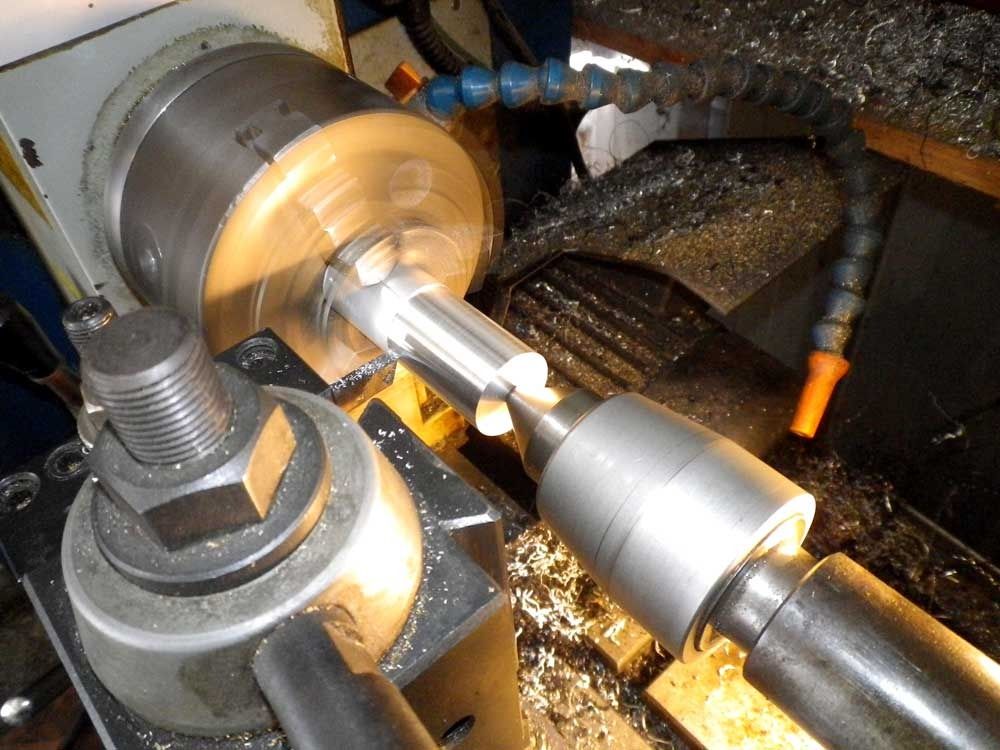
Then I turned the outside to finished dimensions.
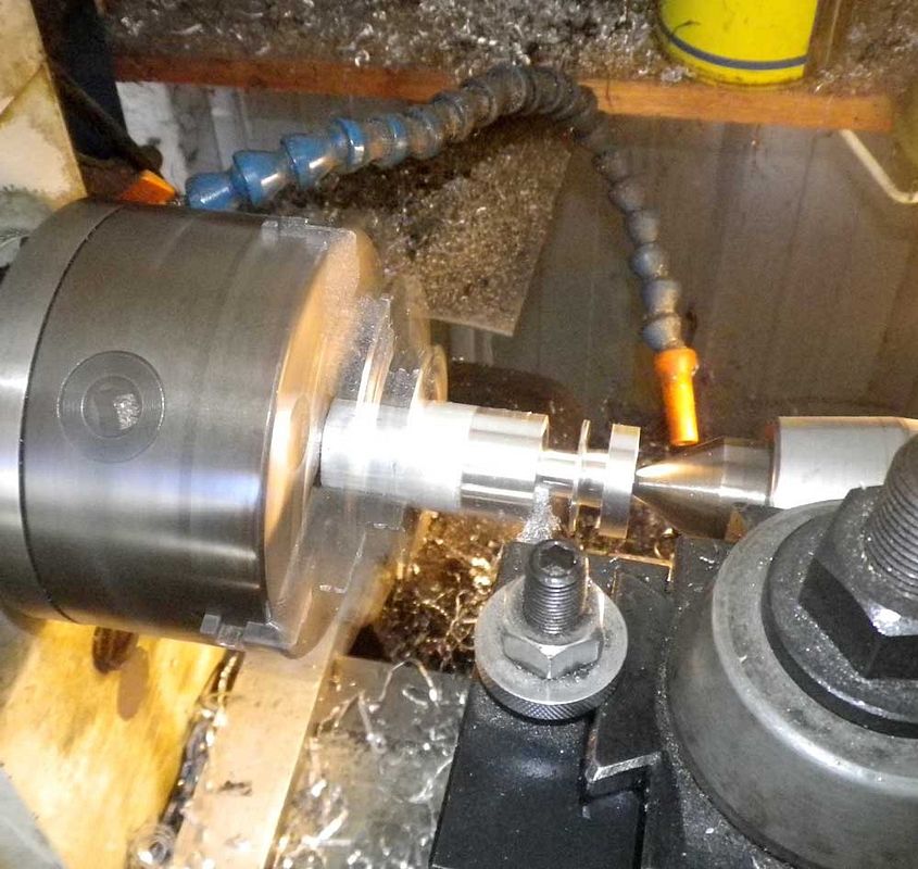
Next I drilled through for the shaft, bored the body out and made the double stepped pocket for the flanged bearing.
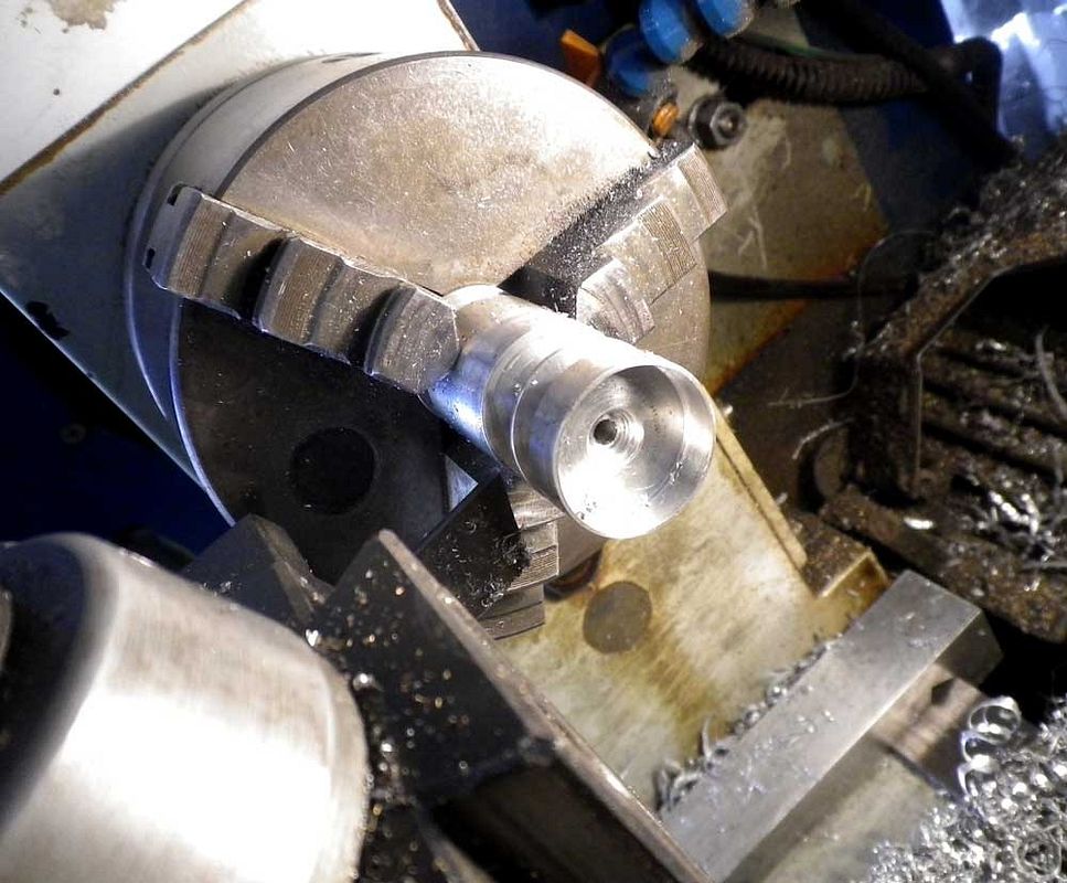
After parting it off I reversed it and lightly gripped it to double step the bearing pocket in the bottom. I used a piece of Monster Energy can to protect the finish but it did get a little marked up.
Once that was done it was onto the mill for making the slot for the hold-down screw and trimming the excess off the hold-down tab.
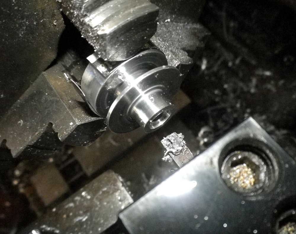
Here's the completed part with bearings installed and mocked up with the cap and drive gear. Again, like all the parts I seem to post, it still needs touching up and polishing, but I think it's a keeper.
That's all I can do until the weather cools down a bit. Hopefully we'll only have a week or two of the really hot stuff.

You are using an out of date browser. It may not display this or other websites correctly.
You should upgrade or use an alternative browser.
You should upgrade or use an alternative browser.
PeeWee V4 slow build
- Thread starter Cogsy
- Start date


Help Support Home Model Engine Machinist Forum:
This site may earn a commission from merchant affiliate
links, including eBay, Amazon, and others.
Cogsy
Well-Known Member
It's small but easy to make. You'll have no problems with it I'm sure.
This engine is starting to get addictive. The more parts I build, the more I want to build. My wife is starting to get a little touchy over the time I'm spending in the shed already and I'm only 2% complete :fan:.
This engine is starting to get addictive. The more parts I build, the more I want to build. My wife is starting to get a little touchy over the time I'm spending in the shed already and I'm only 2% complete :fan:.
- Joined
- May 27, 2010
- Messages
- 2,999
- Reaction score
- 1,171
Hi Cogsy,
When you get so near to completion,its about time to take it easy. Take Care.
When you get so near to completion,its about time to take it easy. Take Care.
Cogsy
Well-Known Member
I managed to sneak the dizzy cap into the house for filing and sanding after all. It took a while but smoothed out reasonably nicely, although it was quite dull, so I hit it with a quick flash with the mapp gas torch. That was a mistake. The posts distorted quickly and the finish isn't what I was after at all. So it's into the trash and now I need to find a suitable piece of Delrin at a reasonable price. Oh well, it was a learning experience.
The weather has been horrible here lately, with 40 degree Celsius days interspersed with a massive thunderstorm that raged over the area for a good 4 hours or so. Our main air-con in the house has decided to blow up (we're waiting on the warranty dept to call us to arrange a time to look at it...) so the house has been almost uninhabitable. On the plus side, it has been easier to spend the odd hour or two in the shed as the temp difference between the house and shed is much closer than usual.
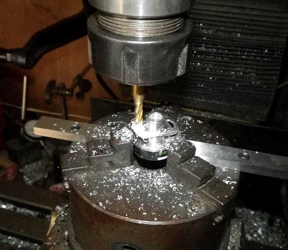
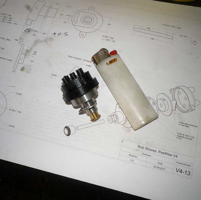
A couple of pieces of simple turning resulted in a magnet disk and rotor blank for the dizzy. Just need some 2-56 grub screws (like hens teeth in Australia), the rotor contact and the trigger magnets to finish these pieces and the inside of the dizzy is complete (except for the electrics later).

Next up I decided to make the timing cover. I machined a piece of 5mm ali plate to 1.6mm and bored some holes in it, then machined a couple of slots before removing it from the rest of the stock with a hacksaw.

The bottom radius is centred on the bottom large hole so it was simple to set up in the dividing head with a bolt through the hole as a pivot. The top radius is centred below the top hole though, so I had to make a jig to mount the piece with the correct pivot point. I bolted it up and used some super-glue to hold it together, then took light cuts and it worked as expected.

Then I turned up the snout for the fan assembly with a flange to locate it in the cover. The whole timing cover and snout is drawn as 1 piece and I did have a go at carving it out of a piece of 3/4" plate, but I wasn't happy with the result (it actually morphed into the jig you see in the photo above), so I made it 2 piece and I've JB welded it together. I hope it'll be strong enough.

The completed part looks like this, although it's now in a clamp while the JB Weld cures.

Finally, some simple turning but extremely difficult drilling and countersinking yielded these 2 fan centres. I only need 1 but again wasn't happy with the first attempt so I made another. I'm not 100% happy with the second one either so I may revisit this piece later. I might also experiment on them with some anodizing dyes I've got stashed under the bench and see what I can do as well.

So that's where I'm at right now. Not much progress but progress nonetheless. Next up I think I'll try the fan pulley and the fan itself, although I'm yet to work out exactly how I'll go about the fan.
The weather has been horrible here lately, with 40 degree Celsius days interspersed with a massive thunderstorm that raged over the area for a good 4 hours or so. Our main air-con in the house has decided to blow up (we're waiting on the warranty dept to call us to arrange a time to look at it...) so the house has been almost uninhabitable. On the plus side, it has been easier to spend the odd hour or two in the shed as the temp difference between the house and shed is much closer than usual.
A couple of pieces of simple turning resulted in a magnet disk and rotor blank for the dizzy. Just need some 2-56 grub screws (like hens teeth in Australia), the rotor contact and the trigger magnets to finish these pieces and the inside of the dizzy is complete (except for the electrics later).

Next up I decided to make the timing cover. I machined a piece of 5mm ali plate to 1.6mm and bored some holes in it, then machined a couple of slots before removing it from the rest of the stock with a hacksaw.

The bottom radius is centred on the bottom large hole so it was simple to set up in the dividing head with a bolt through the hole as a pivot. The top radius is centred below the top hole though, so I had to make a jig to mount the piece with the correct pivot point. I bolted it up and used some super-glue to hold it together, then took light cuts and it worked as expected.

Then I turned up the snout for the fan assembly with a flange to locate it in the cover. The whole timing cover and snout is drawn as 1 piece and I did have a go at carving it out of a piece of 3/4" plate, but I wasn't happy with the result (it actually morphed into the jig you see in the photo above), so I made it 2 piece and I've JB welded it together. I hope it'll be strong enough.

The completed part looks like this, although it's now in a clamp while the JB Weld cures.

Finally, some simple turning but extremely difficult drilling and countersinking yielded these 2 fan centres. I only need 1 but again wasn't happy with the first attempt so I made another. I'm not 100% happy with the second one either so I may revisit this piece later. I might also experiment on them with some anodizing dyes I've got stashed under the bench and see what I can do as well.

So that's where I'm at right now. Not much progress but progress nonetheless. Next up I think I'll try the fan pulley and the fan itself, although I'm yet to work out exactly how I'll go about the fan.
Last edited:
canadianhorsepower
Well-Known Member
- Joined
- Oct 22, 2011
- Messages
- 1,671
- Reaction score
- 324
[quote managed to sneak the dizzy cap into the house for filing and sanding after all. It took a while but smoothed out reasonably nicely, although it was quite dull, so I hit it with a quick flash with the mapp gas torch. ][/quote]
I use clear nail polish on plastic it gives a great finish
good job on the motorThm:Thm:
I use clear nail polish on plastic it gives a great finish
good job on the motorThm:Thm:
Hi Al, I have used black acetal(delrin) with great success for some of my astronomy adaptors.Cogsy said:Maybe I used the wrong sort of plastic. Can anyone suggest a plastic that turns easily and finishes nicely?
This stuff machines beautifully with HSS tooling, I can't speak with any authority about how it behaves with inserts, but I have used an insert for threading (M48 x 0.5 internal) and it was easy peesy with excellent finish.
Like Paul(Swifty) I got the acetal from dotmar, they're located in Canning Vale over here, but they have a MOV which from memory was about $70 or something.
I have quite a lot of 60mm round, if you need any and you're ever around the Canning Vale area, give me a yell.
Last edited:
Cogsy
Well-Known Member
Thanks for the offer Simon, I might just take you up on that. Funds are a little tight at the moment to spend $70 on stock but I'll gladly buy an offcut from you.
I'll drop you a line when I'm headed out that way. Cheers.
I'll drop you a line when I'm headed out that way. Cheers.
Cogsy
Well-Known Member
100mm would be heaps. Really, the dizzy cap is only about 1" tall plus a bit to grab in the jaws of the chuck. Thanks again.
Cogsy
Well-Known Member
With the thunderstorms keeping the temp down, today was a perfect day to get into the shed. It's a pity then that the kids start the new school year tomorrow so the wife had me doing all sorts of things to prepare for that adventure. I did sneak a couple of hours though.
I made the fan pulley and it turned out to be the very first part on the Peewee that I didn't have to make 2 of. Yet. I have to learn to take better photos, it does look good in the flesh, I promise.

The bolts to hold the fan in place are tiny little 0-80's and as I'm mainly a metric guy, I had to buy taps and dies for this imperial engine. I toyed with the idea of just buying the sizes I needed, but in such small sizes it has to be online and I couldn't be sure of the quality of Dubro, etc. So in the end I took a risk on this kit from Chronos in the UK. I believe it's Chinese as we have an Aussie seller here selling the same kit that solely deals in Chinese stuff. I don't like him as a supplier (he's the guy in Adelaide for all the Aussies on the forum) and Chronos was within $0.50 of the price including shipping anyway. So far it's been absolutely brilliant. I've tapped 00-80 in Aluminium, 2-56 in ali and steel and externally threaded 0-80 on drill rod. The kit includes taper and bottoming taps in each size and the handle holds well and keeps straight. If you need a cheap small tap and die set (it's billed as a watchmakers set) I'd recommend it.

No photo but I did try and rough out a fan in ali. I got something resembling a fan and a reasonable machining process that should make me a decent fan, but trying to angle the blades I destroyed it. I'm not sure yet whether I'll switch to steel or brass instead, or try and 3D mill the blades with the angle included - without CNC. We'll see how I feel when I get back in the shed.
Last edited:
So in the end I took a risk on this kit from Chronos in the UK.
.......
So far it's been absolutely brilliant. I've tapped 00-80 in Aluminium, 2-56 in ali and steel and externally threaded 0-80 on drill rod. The kit includes taper and bottoming taps in each size and the handle holds well and keeps straight. If you need a cheap small tap and die set (it's billed as a watchmakers set) I'd recommend it.
Ha!
A few weeks ago I took the risk and bought the metric version and like you I would recommend it.
Years ago when I was managing a Jaycar store these kits came in as a new product and I immediately dismissed it as junk.
Then a month ago I was looking for tiny metric taps and dies and worked out that pretty much the only decent thing out there was a Bergeon watchmakers set, which at around $1000 was not going to happen.
I then looked at these cheap sets on ebay and remembered Jaycar. Turns out the Jaycar price is better than eBay, surprisingly, and I can have instant gratification( no waiting weeks for delivery from China), have a good look before buying and even return them hassle free if I didn't like them after trying.
Looking at the taps under a x10 loupe, they looked OK so I had a look at the dies and decided they were very rough but I'd give them a go anyway..... well, I'm impressed, very.
I'm yrt to try the taps, but as junky as the dies look, the finish on a thread under a x10 loupe is pretty damned good considering the tiny size.
$1000 Bergeon good? No way, but at ~$60 for 9 dies and 18 tiny taps of acceptable quality, I'm a very long way from complaining!!!
I just wish I'd given them a chance when I was working there to get the staff discount, which at Jaycar is very generous (can be as much as 75% off on some stuff)
http://www.jaycar.com.au/productView.asp?ID=TD2443
Last edited:
Cogsy
Well-Known Member
Next up, for no particular reason, I'm attempting the water pump. First piece is the pump body.
I didn't really put enough thought into the order of machining ops and realised fairly early that I'd messed up so I started again.
The second one was virtually finished (although I wasn't entirely happy with the internal finish - but I would probably have used it) then I managed to ding the OD with the chuck jaws on the final op. I used pieces of aluminium can to try and protect the finish, but must've over tightened the chuck.
For the third try I machined up a jig to hold the delicate part for it's final op and I got it done. Although the pictures aren't great, the internal finish is much better on the final one.
So here they are left to right is 1st, 2nd, 3rd.


The internals, fittings, backing plate and pulley are still to come and next on the list.
Last edited:
I know the feeling of the 3 in 1 part, your doing a good job, keep up the good work
By the time the new castings arrive you will have most of the parts made")
By the time the new castings arrive you will have most of the parts made
Cogsy
Well-Known Member
Thanks Michael. I don't know about that though, it feels like I have done a lot of work but my completed parts pile is pretty small. I really need to stop making so many of the same things when I only need 1 good one.
Cogsy
Well-Known Member
It took far more effort than I thought it would, but I finally managed to cram two 9 tooth spur gears into the water pump body. It seems I didn't take any photos of them in there but trust me, they are in place.
Then a reasonably simple backing plate and a drive pulley and the water pump is complete, except for the small o-ring to seal the shaft.

And here it is actually pumping water! It pumps more than the picture makes it look, in fact I'm thinking I may need to restrict it further. It was a real pain trying to take this shot and run the drill at the same time. I took several and this was the best. I may make a short video to better show how it pumps.

That's all for now - that 'simple job' took me 4 trips to the shed over 4 days to complete. Not sure what to start next. I'll study the plans more and see what jumps out at me.
Last edited:
- Joined
- May 27, 2010
- Messages
- 2,999
- Reaction score
- 1,171
Hi Cogsy,
Please take a shot of the gears in mesh. Gus will be making same gear type lube oil pump for the
Howell V-2 Engine.
Please take a shot of the gears in mesh. Gus will be making same gear type lube oil pump for the
Howell V-2 Engine.
Cogsy
Well-Known Member
No worries Gus. Might not be today - I have visitors staying, but will get it done for you.
Hi Cogsy
Looking great, what gears did you use? The ones on then plans require you buy a 3 foot length!!! As I'm in Thailand and the gear stock is in the US I don't teally won't to buy 3 feet when I only need maybe 1 inch, have you come up with a different solution.
Thanks
Dave
Looking great, what gears did you use? The ones on then plans require you buy a 3 foot length!!! As I'm in Thailand and the gear stock is in the US I don't teally won't to buy 3 feet when I only need maybe 1 inch, have you come up with a different solution.
Thanks
Dave
Cogsy
Well-Known Member
Hi Dave
I bought a 1 foot length from the US when I bought the bevel gears for the distributor. It is true that you technically only need about an inch of it if all goes well, but I used nearly 2 inches trying various things and then there is also some slight damage to a section where it was clamped in the jaws of the chuck (probably could still be used though).
I could always post you an inch or so but Aust post is expensive to ship overseas, so for probably not much more you could get a whole foot, especially if you're also going to buy other gears at the same time. I found SDP-SI to be the cheapest supplier and they had everything I needed in one order. Plus, they're completely online, freight is calculated automatically and everything.
Anyhow, if you need me to I can find out a shipping cost to Thailand and send you some gear stocl. Let me know if you need it.
- Joined
- May 27, 2010
- Messages
- 2,999
- Reaction score
- 1,171
Hi Cogsy
Looking great, what gears did you use? The ones on then plans require you buy a 3 foot length!!! As I'm in Thailand and the gear stock is in the US I don't teally won't to buy 3 feet when I only need maybe 1 inch, have you come up with a different solution.
Thanks
Dave
Hi Dave,
2---4 weeks from now I am cutting Module 0.8 Spur Gears for the
Howell V-2. Please email gear drawings. CTC does stock Imperial Gear Cutters. I have Module 0.8 and 1 Gear Cutters.
Similar threads
- Replies
- 2
- Views
- 830
- Replies
- 5
- Views
- 1K
- Replies
- 14
- Views
- 3K