
You are using an out of date browser. It may not display this or other websites correctly.
You should upgrade or use an alternative browser.
You should upgrade or use an alternative browser.
PeeWee V4 slow build
- Thread starter Cogsy
- Start date


Help Support Home Model Engine Machinist Forum:
This site may earn a commission from merchant affiliate
links, including eBay, Amazon, and others.
I may take you up on your offer of sending but I will check your supplier first, I been trying to find a cheaper source for the bevel gears as they are very expensive, I will get back to you, did you get your new castings yet?Hi Dave
I bought a 1 foot length from the US when I bought the bevel gears for the distributor. It is true that you technically only need about an inch of it if all goes well, but I used nearly 2 inches trying various things and then there is also some slight damage to a section where it was clamped in the jaws of the chuck (probably could still be used though).
I could always post you an inch or so but Aust post is expensive to ship overseas, so for probably not much more you could get a whole foot, especially if you're also going to buy other gears at the same time. I found SDP-SI to be the cheapest supplier and they had everything I needed in one order. Plus, they're completely online, freight is calculated automatically and everything.
Anyhow, if you need me to I can find out a shipping cost to Thailand and send you some gear stocl. Let me know if you need it.
Cogsy
Well-Known Member
No news on the castings yet  . Fingers are still crossed.
I'll find out a shipping cost for you to send a piece of the gear stock.
Gus - the gears for the water pump are 32DP (so close to 0.8 mod) but are only 9 tooth. As far as I know the cutter for the smallest gear only goes down to 12 tooth so it wouldn't cut a 9 tooth gear.
. Fingers are still crossed.I'll find out a shipping cost for you to send a piece of the gear stock.
Gus - the gears for the water pump are 32DP (so close to 0.8 mod) but are only 9 tooth. As far as I know the cutter for the smallest gear only goes down to 12 tooth so it wouldn't cut a 9 tooth gear.
Cogsy
Well-Known Member
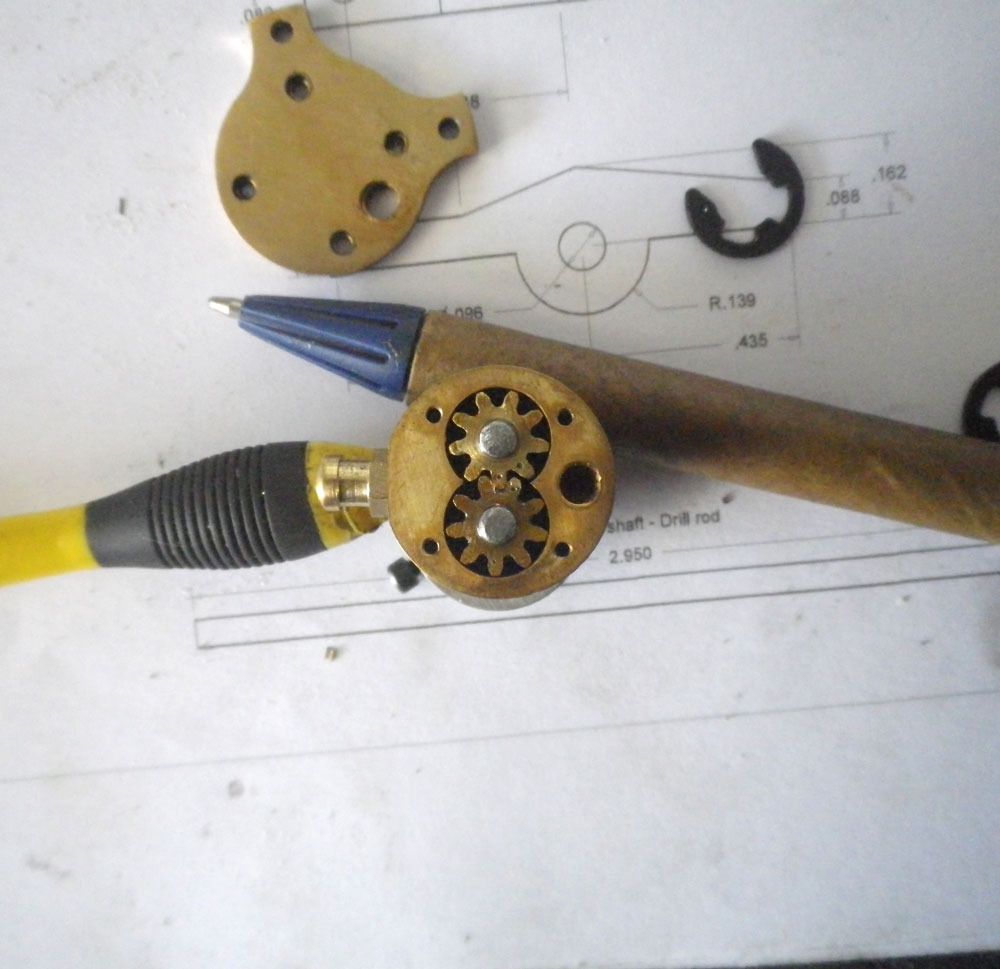
Please take a shot of the gears in mesh.
Here you go Gus - better late than never (I nearly forgot:hDe
. The punch marks are for 'timing'. I figured I ran them in in this particular configuration so they might as well stay in the same config.
I may take you up on your offer of sending but I will check your supplier first
Postage isn't all that bad depending on the size of the parcel it will go in (thickness not weight). Somewhere between $2.50 and $10.00 so if you need it then it's definitely do-able.
Last edited:
Nice work Cogsy, I might tackle the water pump next, as I am not happy with my crankshaft and am waiting for new bar stock to arrive from the UK, I would like to take you up on your offer, if you could send me enough gear stock for the two gears that would be great, please let me know what the cost is so I can reimburse you, is PayPal OK?
Here you go Gus - better late than never (I nearly forgot:hDe
Nice work Cogsy, I might tackle the water pump next, as I am not happy with my crankshaft and am waiting for new bar stock to arrive from the UK, I would like to take you up on your offer, if you could send me enough gear stock for the two gears that would be great, please let me know what the cost is so I can reimburse you, is PayPal OK?
Postage isn't all that bad depending on the size of the parcel it will go in (thickness not weight). Somewhere between $2.50 and $10.00 so if you need it then it's definitely do-able.
Cogsy
Well-Known Member
No worries Dave. I'll suss it out and PM you.
What steel are you making the crank out of? I used 1144 stressproof that I ordered off Amazon and it cuts beautifully. I just used some 12L14 for the first time and am hard pressed to tell the difference in machinability, except the 1144 makes smaller chips (almost like cast iron). If you can get 1144 I heartily recommend it.
What steel are you making the crank out of? I used 1144 stressproof that I ordered off Amazon and it cuts beautifully. I just used some 12L14 for the first time and am hard pressed to tell the difference in machinability, except the 1144 makes smaller chips (almost like cast iron). If you can get 1144 I heartily recommend it.
hi Cogsy.No worries Dave. I'll suss it out and PM you.hi Cogsy.
The crankshaft is built u from parts, so I'm using drill rod for the journals and main shaft, I bought some steel bar stock locally for the webs not sure what it is but it is very hard, anyways I messed up the alignment of the holes so I going to make new webs once the new bar stock from the UK arrives, I bought free machining steel for the new webs, I will post some pics soon.
Dave
What steel are you making the crank out of? I used 1144 stressproof that I ordered off Amazon and it cuts beautifully. I just used some 12L14 for the first time and am hard pressed to tell the difference in machinability, except the 1144 makes smaller chips (almost like cast iron). If you can get 1144 I heartily recommend it.
The crankshaft is built u from parts, so I'm using drill rod for the journals and main shaft, I bought some steel bar stock locally for the webs not sure what it is but it is very hard, anyways I messed up the alignment of the holes so I going to make new webs once the new bar stock from the UK arrives, I bought free machining steel for the new webs, I will post some pics soon.
- Joined
- May 27, 2010
- Messages
- 2,999
- Reaction score
- 1,171
No worries Dave. I'll suss it out and PM you.
What steel are you making the crank out of? I used 1144 stressproof that I ordered off Amazon and it cuts beautifully. I just used some 12L14 for the first time and am hard pressed to tell the difference in machinability, except the 1144 makes smaller chips (almost like cast iron). If you can get 1144 I heartily recommend it.
Hi Cogsy,
Will try out 1144 for crankshafts meanwhile I am using Bright Mild Steel Bars from the regular bar stock supplier. BMS been used for my Webster, Rupnow and Nemett-Lynx w/o any problems so far. Guess I am lucky. Also used Japanese 5-----8mm o.d bar stocks bought from TokyuHands. They machine well. Shy to say they are to J.I.S.. Specs unkown.
Copy Cat Gus learning from HMEM Veterans/Experts.
Cogsy
Well-Known Member
Same as you Gus, I've always just used what I had for crankshafts, but I've always just made built-up type cranks before. For this one being a one piece, I needed better material that was less likely to warp from internal stresses as it was machined so I went with the 1144. It was a pleasure to find out how easy the stuff machines - so much so that I'll be ordering more and using it instead of other steels where practical.
- Joined
- May 27, 2010
- Messages
- 2,999
- Reaction score
- 1,171
Please post when the multi-throw crankshaft is WIP and when done. Todate I still shy away from such c/shafts.
Looking forward to learn from Meister Cogsy.
Looking forward to learn from Meister Cogsy.
Cogsy
Well-Known Member
Please post when the multi-throw crankshaft is WIP and when done.
Not sure I'm really the one to be learning from but the crankshaft was completed back in post number 70. There were some WIP updates but it took me 2 tries to make a useable crank.
It was a stressful job but a huge amount of satisfaction once it as done. I will make more 1 piece cranks in the future.
Cogsy
Well-Known Member
It's been a while since my last post. I've been distracted building myself a small furnace and playing with casting a little bit but I'm back on to the Peewee for now.
The Peewee castings are still in limbo at the moment so I'm still working on the little bits and pieces I can do without the castings. First up I decided the rocker arms looked reasonably simple.
In theory the arms could be carved out of a piece of 1" 12L14 round bar that I have in stock, but the stock would need to be offset in the 3 jaw on my dividing head. I had a couple of attempts (and wasted over a foot of stock) at trying to set the offset plus square the tailstock and the bar itself to the mill. Tough to explain but it was too difficult to get right so I moved on to my backup plan - cutting them out of a 1-1/4" piece of tool steel I inherited.
Once the stock was squared I took it down on the first side and milled a series of steps with the dividing head to get the rounded central profile.


Then rotated it 180 degrees, took down the other side and used the dividing head to machine in the correct top angles.

From there it was a relatively simple matter of drilling the pivot hole, parting off and drilling/tapping the adjuster screw.

Although this is a small bunch of less than impressive looking parts, the problematic setups and absolutely horrible-to-machine tool steel meant that it took a lot longer to make these than it should have. I haven't worked out a better way to make them yet but I'm sure I went about it all wrong.
Last edited:
Cogsy
Well-Known Member
I was inspired by Gus when he explained he was taking care of some of the 'fiddly' parts of his V twin build early in the build so he didn't rush them at the end. I often suffer from the same sort of problem so with that in mind I decided to start building the carb.
It seemed a little daunting looking at the plans but really wasn't too hard to make.
I started by roughly offsetting a piece of 3/4" ali in the 4 jaw and turned the two round sections.

Then milled each of the 4 sides. Each side had 2 steps in it so it was really 8 sides, but really straightforward milling.

Back in the lathe for the boring of the drum cavity.

Then drilling and tapping the various holes in the body. The plans call for an air bleed hole to be drilled with a number 70 drill, then test the carb on the engine. If it leans out at full throttle then the hole needs to be opened up to the next size and re-tested. Repeat until it's right. Instead of this procedure, I've borrowed Steve Huck's idea and drilled and tapped a 4-40 hole instead. Eventually I'll make a series of small 'bolts' with different size holes in them to get the bleed hole size right without the danger of going too big or snapping a tiny drill bit off in a completed carb.
The plans also call for a .070" hole to be drilled completely through the back of the carb, then each end opened up and threaded 2-56. One side is for the fuel inlet and the other side is for the needle, which is supposed to act on the 0.070" section in the middle. Instead of this I drilled and tapped 2-56 all the way through and I'll have the needle act on the end of the fuel inlet instead. It seemed an easier and safer way to make it so I hope it works and I haven't overlooked something important.

After turning the drum (no pictures of that but very straightforward) the drum was clamped into the carb and the carb was centered on the mill and bored through the body and drum. Then the drum was removed and the throat opened up.

Next I parted the carb off it's parent stock, shaped the bottom flange freehand with a file and made and fitted a throttle stop and fuel inlet.

Next up, the needle.
Last edited:
Cogsy
Well-Known Member
The carb needle is a hand-sewing needle about 1.2mm (0.047") in diameter, fitted into a brass adjusting screw.
To start I turned and threaded a piece of brass 2-56 - actually it's the guts of a garden tap. I ran out of brass stock and had this laying around so I cannibalised it. Then I peck drilled with a 1.2mm drill bit, 0.25mm at a time for the full length, about 9mm. Here it is with the sewing needle test fitted.

Then I knurled the end as I won't be able to slot the head with the sewing needle embedded in it.

Once I parted the piece off I chucked up a piece of ali and dilled and tapped it 2-56 to use as a mandrel. I drilled it extra deep as the screw will need to screw into it with the needle attached eventually. This allowed me to shape and clean up the end, and to countersink a slight recess for solder to bed into.

To solder the needle in the correct place I first tightened the screw all the way in, then backed it off about 1-1/2 turns. Then I inserted the sewing needle all the way through and made sure it was fully closing the fuel inlet and soldered it in place. This means I can fully close the needle and have it completely block the fuel off, giving me the absolute maximum amount of adjustment. It also guarantees correct alignment of the needle to the fuel inlet.

This is the nearly completed needle. I just needed to trim the excess needle poking out the back of the screw, then stick it back in the mandrel and carefully clean up the end with a file and sandpaper.

Here is the completed carb except for the air bleed 'bolts' I mentioned earlier, a throttle arm and of course the obligatory clean and polish.

Next up - I have no idea and my posting has again caught up to my building so it could be a while...
Last edited:
Swifty
Well-Known Member
Nice job Cogsy, I have loctited the needle in before, with no problem.
Paul.
Paul.
- Joined
- May 27, 2010
- Messages
- 2,999
- Reaction score
- 1,171
Hi Cogsy.
Great job on the Jet Needle. Did same for the Nemett-Lynx Engine. Used Loctite to hold sewing needle.
Was looking for ways to make same as per Jerry Howell's drawings. Will post later today.
I have yet to DIY a knurling tool. The knurls are on the PC Desk begging me to put them to use.:rant:
Great job on the Jet Needle. Did same for the Nemett-Lynx Engine. Used Loctite to hold sewing needle.
Was looking for ways to make same as per Jerry Howell's drawings. Will post later today.
I have yet to DIY a knurling tool. The knurls are on the PC Desk begging me to put them to use.:rant:
Cogsy
Well-Known Member
I wasn't sure loctite would work. I thought maybe the fuel would dissolve it over time. Now I know it works I'll probably use it for ease next time.
- Joined
- May 27, 2010
- Messages
- 2,999
- Reaction score
- 1,171
Hi Cogsy,
No worries. I loctited the sewing needle for the Nemett-Lynx Engine. The Carb is not expected to get very hot and no danger of needle falling out.
I am taking too much sweet time with the Howell V-2 Carb. Going a snail pace but enjoying the work and finishing.Carb body now mounted on to O/Head and waiting for the throttle barrel. Just figured out a way to machine the barrel.
Cogsy
Well-Known Member
I managed to get a little shop time and make the throttle arm and screw, plus one of the little 'bolts' for the air bleed hole. I'll make a few of them and drill them various sizes once I get a micro drill set.
This completes the carb and I'm looking at attempting the camshaft next. First I need to make the fixture but that's a story for another day.

This completes the carb and I'm looking at attempting the camshaft next. First I need to make the fixture but that's a story for another day.

Last edited:
Looking good Cogsy, you will soon have all the parts made
Similar threads
- Replies
- 2
- Views
- 830
- Replies
- 5
- Views
- 1K
- Replies
- 14
- Views
- 3K