My First Build - The EZ engine

Home Model Engine Machinist Forum

Help Support Home Model Engine Machinist Forum:

This site may earn a commission from merchant affiliate links, including eBay, Amazon, and others.
Cheers Marv, that's brilliant, I can see that a pump center would make life so much easier. I found more examples with the search. I'll knock one of these up before I do the next offset hole. I took so much time yesterday faffing about with the set up I didn't get much further along. I was almost embarrassed to show what little progress I'd made but I was sure there would be a better way to do it.

Nick
 
Finished the cylinder off today.

First job was to open up the pilot hole with a 10mm drill this gives me enough clearance to get a boring bar into the hole. Any tips for tooling for boring in small holes much appreciated?

Here is the finish of the drilled hole

hole.jpg


Here we are about to start the boring process. This miniature boring bar comes from Chronos Ltd it's made by Glanze, its 5.5mm. It needs plenty of packing up to fit into my Dixon tool holders, only the first two bolts grip on it.

boring.jpg


Being so small it is a bit springy. So it needs a few passes without adjusting the cut to reach the final size. This can make holes go bigger than expected if you wind in cuts without taking out the spring before measuring the diameter. Just to right of the frame and slightly out of focus you can see an example of the square top bolts I made to replace those missing from my tool post. (My first use of a 4 jaw chuck, not this big one as they are too small for it to grip).

Here is the finished bore, the finish is much improved from the drill, I hope it will be good enough. I used the auto feed to keep the tool moving at a constant rate. Stopped the lathe when the tool was full inserted to change the direction of the feed and then cut the other way backing out the tool at the same cut. I don't have any tiny HSS boring tools yet and these would probably get a better finish. I find that with these insert tools that too slow a feed gives a poor finish on steel. I put neat cutting oil in the hole too, this improves the finish.

boredone.jpg


Finally I finished off the part drilling the two fixing holes and the air hole.

block.jpg


I was really pleased to find that all it fitted. And that blowing air into the hole it expells through the cylinder. Those two old battered 3mm screws are pressed into action again to test fit the part. I thought I had done a great job but then when I picked up the stock from the bench to make the valve I realized I'd gone and drilled the cylinder into the (slightly longer) stock piece meant for the valve. Not a big deal it won't affect the engine but I'm annoyed with my self for going off piste! Measure twice and all that, add note to self "check your marking up the right bit of metal too".

I think I'll make the piston next, it was so nice pottering in the workshop playing with the lathe today. Starting to look a bit like an engine now!

Nick


Its coming along nicely. Why is it that we can do our best work in the wrong chunk of metal????
 
I think you're coming along just fine, Nick. The bore in the cylinder looks good in the pic.

Any tips for tooling for boring in small holes much appreciated?

You can grind them up from HSS blanks without much trouble. It's what I use for very small holes.

smallboringbar1.jpg


This one is from a 3/16" square HSS bit, and will go into holes down to about .150" diameter.
Here's a closer shot of the tip. It's about ready for a touch up on the stone, but you can get the idea:

smallboringbar2.jpg


Another good source for small boring bars is HSS end mills. If you lay a 2 flute on the table and roll it until the wide end of one flute is facing straight up at you, you can easily imagine it being the end of a small boring bar. Grind away some of the other flute so it fits in your hole, and a little off the flute behind what will be the cutting end so it doesn't rub the edge of the hole, and you've got it. Sorry, I don't have a pic handy for one of those.

Dean
 
Thanks for the moral support Swarf Rat, you've been there and done that too then, glad I'm not the only one!

Thanks Dean for boring bar info, great reference pics, I'll use them to have to have a go at grinding up some of my own. Yep I think I understand what you mean about grinding an old two flute endmill.

Well today I switched my focus to the piston. Here are some photos and a bit of dialogue as to how I went about making it.

The first job was turn down a piece of stock to just a fraction too big. As I don't have any decent way to measure the inside of holes accurately yet. I cut a small shamfer on the leading edge until the stock would just locate into the bore. This gave me a good guide as to how deep a cut would be to small.

Here is a photo to show the idea.

almost.jpg


Infact in this shot I have already cut some of the shamfer away.
I then crept down on the bore dia a tho at a time until I could do this with the cylinder.

there.jpg


Once I had the size of the piston it was a simple job to machine the end down for the connecting rod to go on to.

Here is a shot of the piston with the lathe tasks completed.

piston1.jpg


and here is shot of the piston sitting in the bore, its a bit dark but quite I like the effect.

piston2.jpg


The fit is pretty good I can feel the vacuum and pressure if I block the air hole and move the piston. With the air hole blocked the piston will only fall into the block very slowly. So I reckon this should be good to go. Just got to machine the conrod connection and it is done.

I also started to cut a replacement piece of stock for the valve part but a short way into the cut I heard a contactor drop out and the saw stopped. I've not worked out why yet and I haven't managed to get it going again. I've checked all the fuses and nothing has blown. I've pressed every thing that looks like a mechanical trip but it is still not playing ball. Will have to give it a good checkover and if it doesn't go tomorrow I might even have to go back to the old manual hacksaw! It did this on me once before and then the next day was a right as rain again so maybe there is something loose in the wiring somewhere. The blade grinder still works OK so it is not suffering a total power loss.

Nick
 
Good news. My saw, which is a DoAll bandsaw (A piccy in my welcome thread if your interested), a three phase mains jobby which weighs loads and stands taller than me, with a tiny blade with teeth rather like a junior hacksaw, is back in the land of the living. Maybe it has got some sort of an automatic thermal/overload trip out and I was pushing it too hard? Given the size of the thing I wouldn't have thought so but hey it's going again now, so parts production can continue, yipee :)

Nick
 
Good going Nick :) - some steady progress Thm:
Don't let the little hiccoughs with machinery put you down ;D

As an aside though; it sounds like you have a fairly substantial saw, and it should not be quitting on you with small cuts like this. Give it a good look-over, and try to find out why it's stopping on you. Something appears to be wrong, and "wrong" things can cause damage - directly or inadvertently.

Regards, Arnold
 
Hi Arnold,

Yep the build is moving along nicely. I made the valve block yesterday. I'll post up some pictures later. I was hunting about in the shop for some more 3mm bolts. I know they are here somewhere but couldn't lay me hands on them last night. Found loads of BA, 4mm and small self tappers. I wish I was a tidy and well organised chap but I'm not and after 51 years of trying to be it's not a lot better now than the day I started!

I've also done a bit more investigation on the saw and I now know what is happening but I don't know why. One of the contactors has a sort of current limit box fitted to it with a lever which set the current limit. The maximum setting is 2.5 amps (which it was set to). Anyway If I just run the saw for a while with no load it will trip out after a minute or two. Normally long enough for me to make any cut I'd want to do in a piece of wood. Once it has tripped it won't reset until it has cooled down. I'm not exactly sure what the current trip is protecting, I'm guessing that it might be the contactor winding current it is protecting. So maybe it just needs a new contactor. I went to a local company Tewkesbury Saw who had an open day yesterday and talked to the owner about it and he has offered to give it a once over for me by one of his electricians so I think I'll take him up on the offer. I'm not very conversant with three phase electrics and I don't want to let the smoke out or more to the point smoke me.

I also took the motor cover off the machine and apart from a thick covering of fine sawdust there was nothing I could see wrong in the motor department. Everything was stone bonkering cold too so it is not a motor overheat type issue. It has two motors one to drive the band and a smaller one to drive the compressor that blows the swarf away.

I can post some pictures if anyone is interest?

Nick
 
Does that motor have a centrifugal switch to disengage the starting coils?
 
Thanks for the thoughts Swart Rat, I see where your going and Ill check its not a sticking motor contact but I'm not sure it does. It has an electronic speed controller with variable speed controller and it has a (very) soft start. The variable speed control works fine before the motor stops.

Well here are a few more steps done on the build.

Yesterday I made the valve body, but as it is very similar to the cylinder machining wise I haven't duplicated the process for you.

Today I made the valve rod and finished off the piston.

Here we are with the lathe in auto feed cutting down a bit of brass to make the valve. It was a slowish feed so I had plenty of time to get some shots I was hoping to capture the chips flying but it didn't really do it justice. I was working on light cuts playing about to get the best finish on the stock. Those specs to the left of the stock are not muck on the lens they are chips, honest!

v1.jpg


I used the same method to get a good fit as I did for the cylinder. Get close, cut a shamfer just smaller than required size, so the valve body would fit onto it and then sneak down on the fit. I had quite a bit of stock hanging out of the chuck and as the bar was getting smaller the free end was starting to spring. I didn't get any steadies with my lathe and I have them on the to make list. Meanwhile I use this method with a piece of wood and take small cuts (I just hold it against the stock whilst the lathe cuts). It does work surprisingly well. I was concious of the size difference between the chuck end and free end and kept taking cuts at the same depth to relieve the spring to get the free end down to the same size as the chuck end.

v2.jpg


Here I am reducing the stock to make the air clearance.The pointed tool I'm using gives a better finish than the one in the first photo above. I chickened out at 4.5mm diameter as it was getting hard to control the spring and I didn't want to stuff up the part.

For such a small piece I found this part quite demanding to make, it took a long time for me to make it. I needed to use different lather tools to face the LH & RH valve lobes. A good learning exercise and all good fun.

The next step was to machine the face for the connecting rod to attach. I did this step in the mill. I kept the part attached to the stock so I had something to hold and also had a test piece to try. Being very new to this I've only ever milled mild steel before today and I want to test how the brass would cut before it became new part affecting.

v3.jpg


I still had this same job to do on the piston and as I now had the end mill cutter depth set it was a simple job to pop the piston in the vblock and cut it down to the same size.

The finally process was to drill and tap the holes for the rods to connect. I'm still finding it hard to get the centers spot on. I think maybe I should used a smaller drill first rather than gone straight in with the tap drill. Close but no cigar.

Anyway here is the final pic for today. The assembled parts on the frame. Yes I found some more 3mm bolts (they are for an aero engine's exhaust mounting so only a temporary loan to this project.) I knew I had some.

v4.jpg


Looking much more like an engine now. I tried a quick test blowing air into the valve block and operating the valve and it works a treat. More round parts to make for the next installment. I'm flying tomorrow so will catch up again next week.


Nick


Nice progress on your build, it's looking good.

Now, I'm starting to wonder if you may have one of the phase drivers dead in your speed controller (either opened or shorted would be likely to make a motor run hotter). I think you may have one phase always energised instead of being cycled at the necessary frequency.
 
Hi Swarf Rat,

Not sure if I gave you a red herring when I said it has a very soft start, I didn't mean to imply that was a symptom of the problem rather it is a feature of how the saw always starts. IE. it doesn't rapidly build up to speed like my lathe does. You could well be right about the problem being controller related.

Anyway thought I'd show you a couple of pics of the panel and point out the thing that trips out.

p1.jpg


And here is an enlargement of the thing that trips.

p2.jpg


Looking at the little white lever it has a rather chewed up end so maybe it has been fiddled about with before. To reset things I have to press the red button but it wont reset immediately I have to wait a while (for it to cool I guess) before it will latch again.

Nick

 
It sounds to me like the circuit breaker is doing its job of protecting the system, something is causing the breaker to trip. Your technician should be able to sort it out quickly with a volt meter. I hope the repair turns out to be quick and easy.
 
My saw is going again now, I found a bad connection on one of the phases so sometimes it was only running on two phase. So well done Swarf Rat you were spot on with you diagnoses.

Well my build has progresses a bit further making all the round parts.

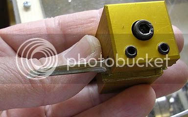
I made the bush a press fit into the frame.

In model flying we have a term hanger rash, which is damage done to an airframe when a model it is not being flown. Is there an equivalent for parts getting scratched or marked after they are finished? If there is then this little brass bush suffered twice! First off when I pushed it into the hole a small piece of swarf scratched as it emerged through the frame. Then later on in the build when I decided to place it to one side rather than mount it centrally in the frame to give more room for the grub screw in the crank wheel, I managed to push it into a square 3/8 socket drive hole, when I needed a shroud around the part so I could press it back through the frame with the vice.

Here we are pre square 3/8 broach marks. (So later on when you see the assembled engine they are not 4 jaw marks.) The axle is still to be cut to final length

r1.jpg


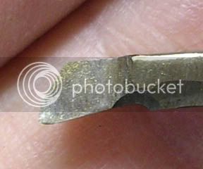
The axle is made from silver steel. It's stock form it was 6.33mm. I currently only have metric drills in 0.1 mm steps up to 6mm. Then I have 0.5mm steps. Well a quick test of 6.33mm axle in a 6.5mm hole gave too much slop so I decided to cut the axle down 5.8 mm so I had some leaway to make free and interference fits of the crank wheel and the flywheel.

I found that it's tough stuff to machine. Being thin I had similar spring issue to making the valve part.

Axel done. Next step was to tackle the fly wheel. I had a suitable piece of ali stock for the part. I put it in the chuck and faced the end, drilled the center hole and clean up the circumference, added the bevels. Everything was going well until I started to part it off. Even though I had the chuck done up tight and plenty of ali to grip, the parting tool cutting caused the part to shift in the chuck so it went out of true. I re-trued by refacing it but then the hole on the center was now not exactly in the center. So once I had finished it I mounted to on the axle as an arbor and trued it up again taking very light cuts. I think I got away with it, next time I will drill the hole last.

With hindsight I think maybe I should of cleaned up the end of the stock and then put that end in the chuck so it could get a better grip? The stock did look nice and round but I guess it wasn't perfect.

Anyway here we are about to clean up the parted face. I'm using a lemonade can kindly donated by one of our hoilday cottage guest's in their recycling bin to stop the chuck marking the part, one of my glass beer bottles wouldn't do the trick! I used the dial gauge on the shamfered rim to make sure the part was running true. As there was not much part to grip I took very light cuts using the cross slide self feed. It gave a nice finish (see below).

r2.jpg


Here is the crank side of the engine. The crank wheel is also silver steel. I found it too hard for my parting tool to cut so parted it with the band saw and then put it back in the lathe to clean it up. It fits to the shaft with a 3mm grub screw. Why silver steel, well it was the only 1 inch round stock I had.

r3.jpg


The finished axle assembly. Piston and valve in their correct position for a change.

r5.jpg


And finally a view of the Flywheel and the rhs of the engine.

r4.jpg


So just the crank and valve rods and their spacers to make and we are ready for a test run. I might build a set in steel first to protype the engine and prove the valve timing and then re make them in brass to give better aesthetics.

The end is in sight. Hope she runs.

Nick


Looking good. Everything looks like it is lining up well.

On the flywheel; I have made a mount for a vise to place it vertically on my band saw so I can cut off thin slices for flywheels from round stock. I have also made flywheels out of flat stock, cut the corners and then put it in the lathe to make it round. Just a preference, but I don't care for parting off large diameters.

Should not be long now! Thm:
 
Thanks for the flywheel tips Black85vette and thanks again to you and the team for designing this training model, I've learnt a heck of a lot from building this engine. I've really enjoyed the process and I have now built my first running engine! Thm:

Well last night I thought I would finish off the last few engine parts but once I'd rough cut two strips of brass from some angle stock I had kicking about and drilled holes in them, I just had to use them in their unfinished state to have a quick play to see if the engine worked. Well I fired up my compressor, set the pressure at 10Lbs, put the air duster attachment on the hose and pressed it over the inlet hole squeezed the trigger and she instantly ran. She was on the induction stroke and just self started and away she went. I then spent the rest of the session just playing about with her. I found that the screws I had cut down and used to hold the crank rod to the crank wheel would gradually self tighten whilst the flywheel screw would gradually loosen, so to continue playing I switched them for their cut off ends.

At the moment I'm just using some 3mm washers for spacers, so one solution might be to make my spacers threaded and use them as lock nuts or maybe I'll just use a bit of thread locker.

I found that I could even get her to run with just a trickle of air. I had a play about with valve timing too.

Anyway here are some pics for you of the engine with rough sawn cranks fitted.

c1.jpg


c2.jpg


c3.jpg


Once I finish up the parts I'll post up a video (that will be a first for me too) and let you see her running. Still to do, I need to make some filling buttons and round the ends of the rods and clean up their rough edges, make the spacers and an air input connection.

Meanwhile a big thanks to all those of you who have have answer my questions and chipped in with advice. For those of you about to take your first steps I hope my build thread has been of some help to get you started.

Nick
 
njl said:
I found that the screws I had cut down and used to hold the crank rod to the crank wheel would gradually self tighten whilst the flywheel screw would gradually loosen, so to continue playing I switched them for their cut off ends.

At the moment I'm just using some 3mm washers for spacers, so one solution might be to make my spacers threaded and use them as lock nuts or maybe I'll just use a bit of thread locker.
Nick
woohoo1

Fine job Nick! Always exciting to get an engine running. Even more so when it is your first.

Great idea about using threading spacers as a lock nut. May have to steal borrow that idea. I may incorporate that into any future designs. Most of the time I use epoxy sparingly on the threads at the final assembly because it sets up so quick.

Looking forward to the video.
 
You know, I really do enjoy seeing these first engines being produced by ,'newbies', for a lack of a better word and not meant as demeaning in any way. It is so refreshing to see and hear of all of the trials and errors that were encountered in their construction and how problems were worked around. I especially enjoy seeing "non-complex" set ups being utilized to good results. Well done, Nick, a fine looking engine. You should be proud of your accomplishments. BRAVO! :D Do you have plans for a second engine? Or another E-Z modified to suit your own artistic style? We are all awaiting your video, oh yeah, don't forget the "happy dance". We are all such suckers for cheap entertainment :big:


BC1
Jim
 
Congratulations Nick!!! Nicely done and a bandsaw repair to boot
 
Sounds like it's going great, Nick. We're all excited to see it chugging along!


Dean
 
Back
Top