Hi All,
I have been reading the various very interesting threads on this forum and thought I might add what I have been doing...
I have always wanted to build a live steam locomotive and during the final year of my engineering degree, a couple of years ago, I thought I might be able to come up with a boiler design, as the first step and the topic for my final year project.
I took this idea to one of my lecturers and he looked at it and said; "Steve I don't think you should design this.... You should design and build it!"
Without having a specific loco in mind I started with some general external dimensions for a 4-6-0 type 5" gauge loco boiler. From there I conducted some research of current design practices and an extensive heat transfer analysis of various fuels and boiler configurations.
One of the objectives of my project was to come up with a design that was efficient as possible based on the heat transfer 'theory'. As I found out, this requires a number of assumptions and is not straightforward. An excellent book on the subject; Steam, its Generation and Use, Babcock and Wilcox, 1978 states on calculating furnace temperatures;
An analytical solution of the problem of heat transfer in the furnace of a steam generating unit is extremely complex. It is not possible to calculate furnace outlet temperatures by theoretical methods alone. It goes on to list factors to be considered such as furnace geometry, fuel variation, surface variation and load as some of the factors that influence temperature. Also; Temperature varies throughout the furnace. Fuel and air enter at relatively low temperatures, reach a high temperature during combustion, and cool again as the products of combustion give up heat to the furnace enclosure. All temperatures change with load, excess air, burner adjustment and other operating conditions.
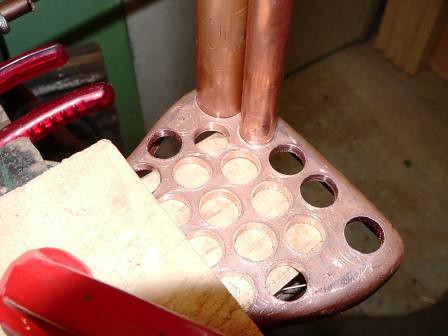
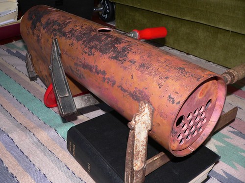
Based on a theoretical load, the completed design would need to produce 10.5kg of steam per hour, at 700 kPa which would require 7.7 kW of energy input. In order to do this efficiently a Firebox with as large a surface area as possible was incorporated. 18 Firetubes were included of 11.1mm ID (Inside Diameter). This was slightly larger than the optimum diameter for heat transfer in order to allow for soot build up and cleaning.
Analysis of the draft design was based on an optimum theoretical efficiency of 82%. This equates to the burning of 1.027kg of Bituminous Coal per hour and an energy input rate of 9.38 kW. Based on these figures the calculated theoretical efficiency was found to be 91.5%. With the aid of these results a detailed design was prepared in CAD. The draft design was developed IAW the AMSBC (Australian Miniature Boiler Safety Committee) Code for copper boilers and in consultation with a certified boiler inspector.
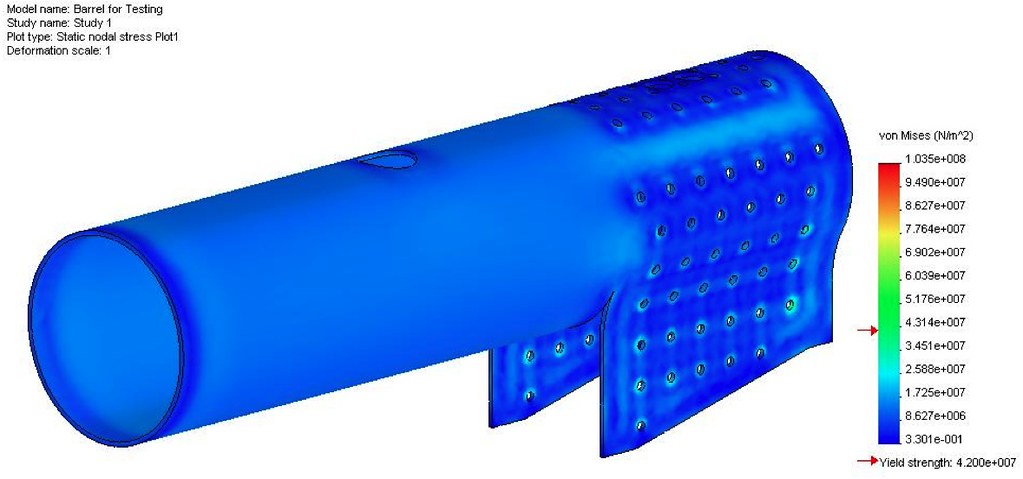
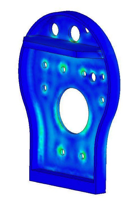
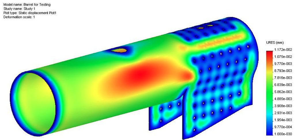
Theoretical and Computational Stress Analysis of the boiler design were calculated and amendments to the design were made as required. The Maximum Shear Stress (Tresca Stress) was found to be 15.87 MPa and the Factors of Safety were calculated for the Boiler and found to be 2.65 against Yielding and 7.1 against Ultimate failure.
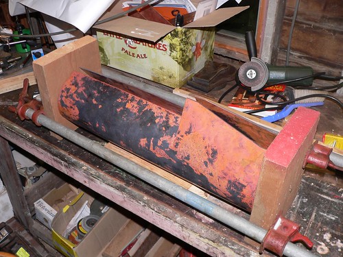
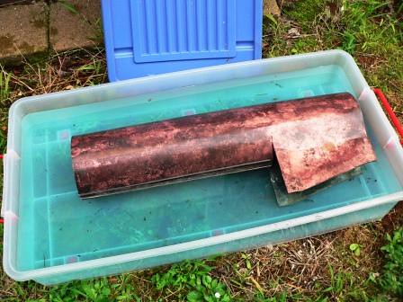
With the design approved material and tools were purchased and construction began with the Waterjet cutting of all copper plate and Laser cutting of 16mm mild steel Formers. All of the boiler plate was formed to shape and the Barrel rolled to the correct diameter. The Butt Strap was Silver Brazed to the Barrel. The Throatplate was fitted with a combination of Bronze and Silver Brazing. All the Boiler Bushes and the components for the Boiler and Regulator were machined to size. The Inner Assembly was completed, passed inspection and fitted into the Barrel.
So over 12 months I embarked on a very steep learning curve that started out as a blank sheet of paper and ended up with a successful hydro test...! As you can see the boiler I ended up with, is not to dissimilar to many standard designs. For the construction the book; "Model Locomotive Boilermaking" by Alec Farmer was always close at hand in the shed and highly recommended.
I had never built anything like this before and it was a real challenge and a very valuable learning experience. For those considering it, have a go, working with copper is great fun.
Here are some images....
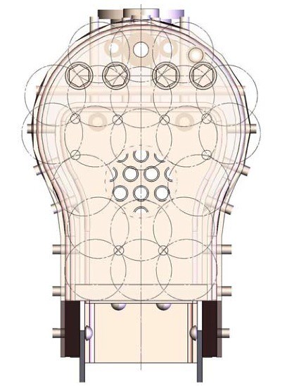
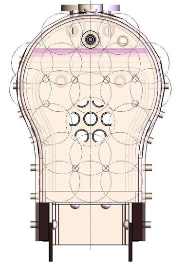
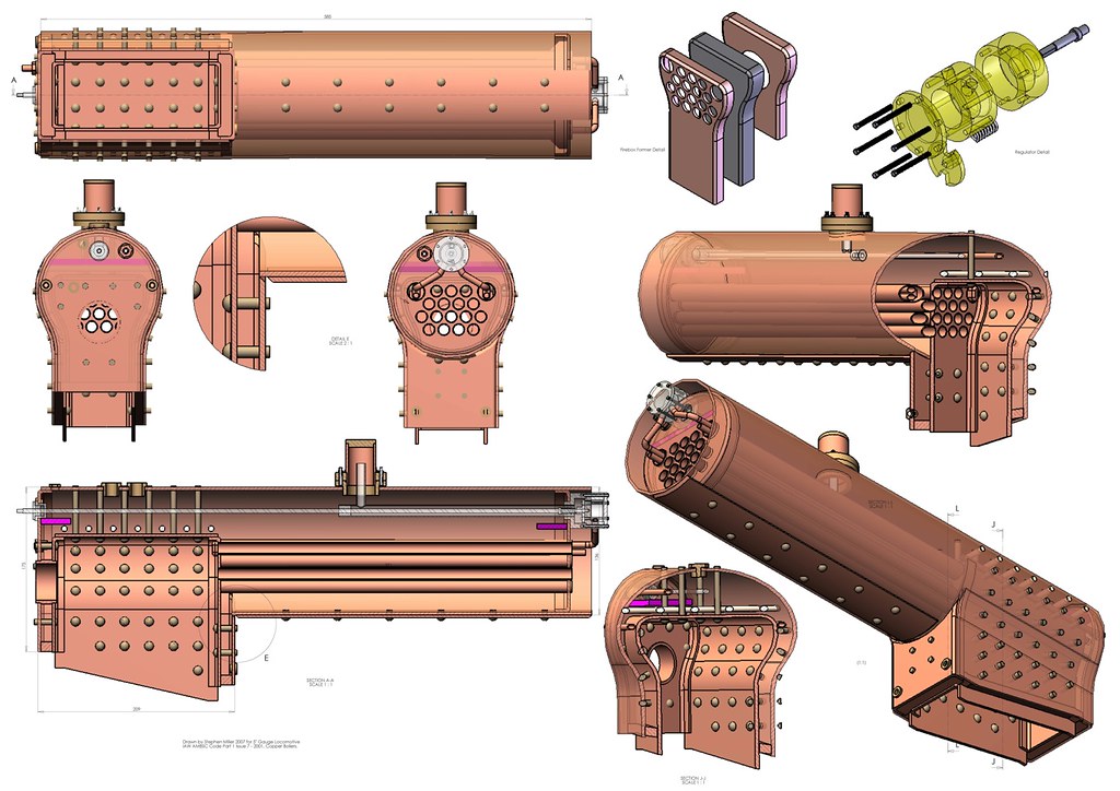
This is the final design, completed with Solidworks 2006
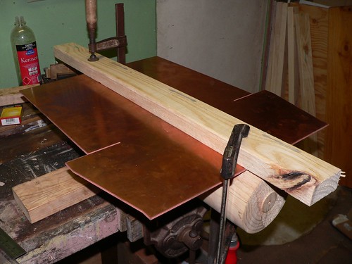
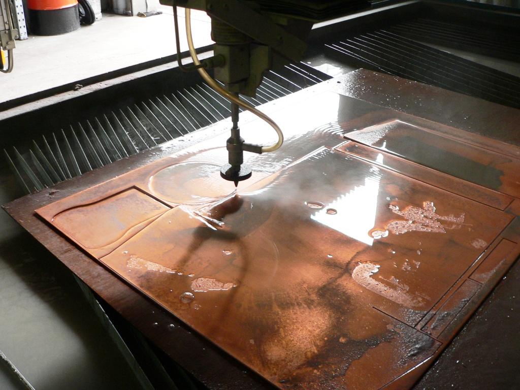
Here are the boiler components being profile cut on a Waterjet machine
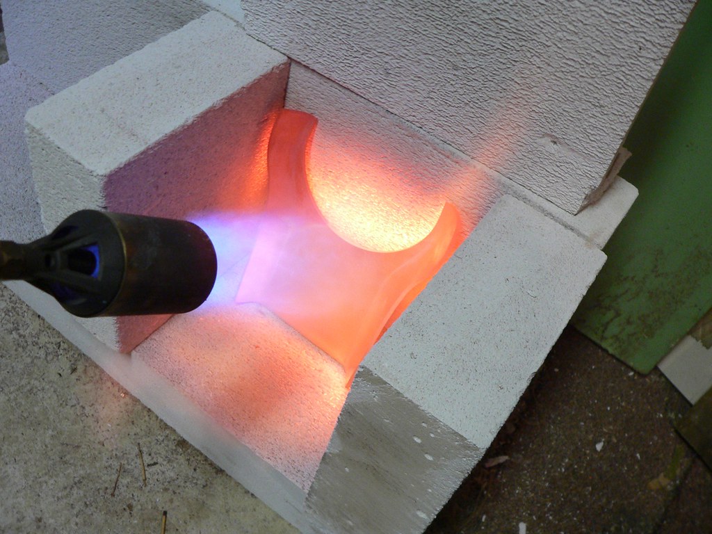
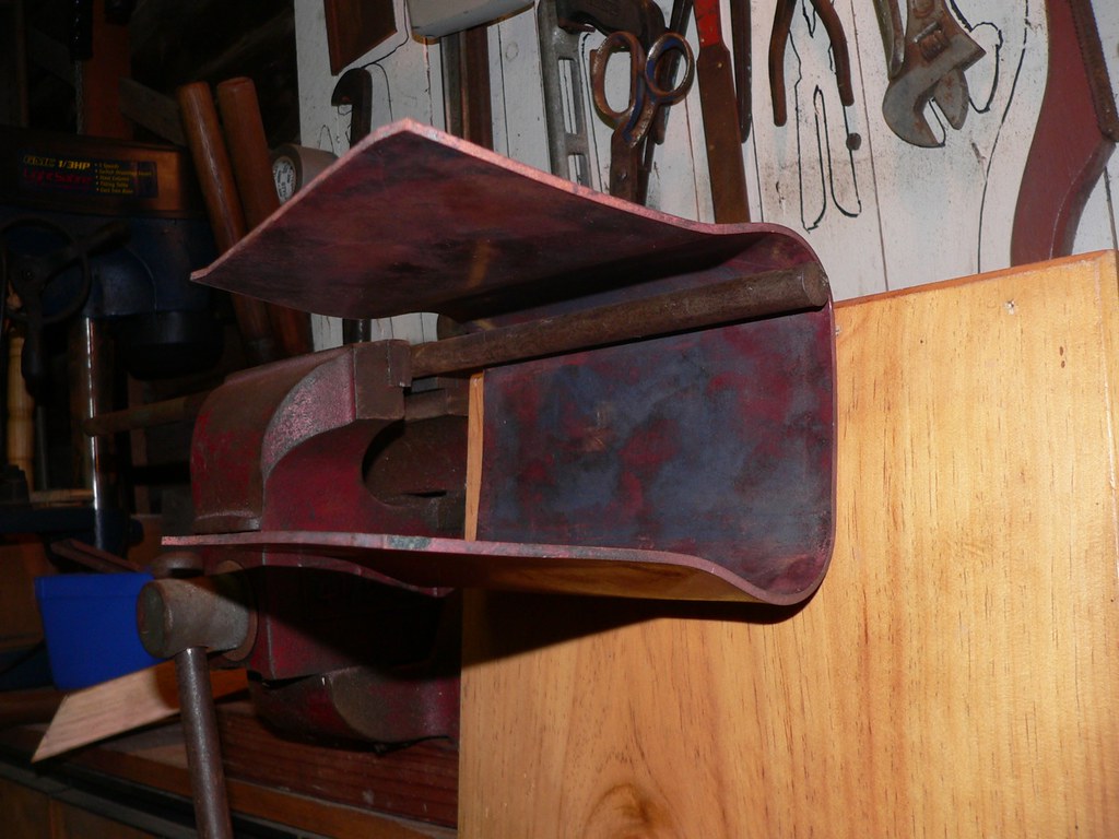
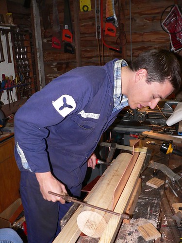
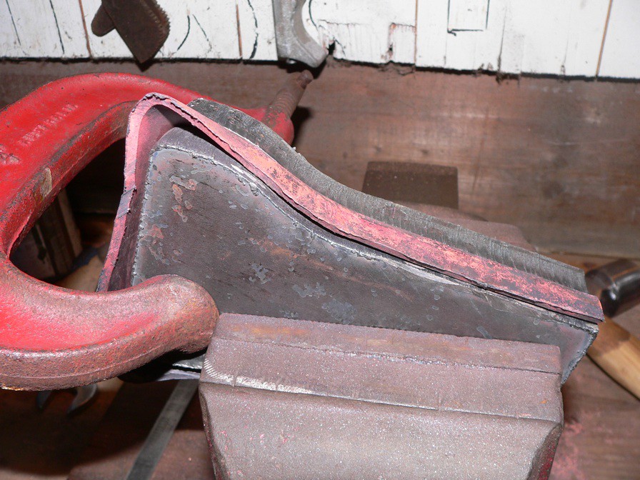
Forming the firebox tubelplate. This required annealing 5-6 times from memory.
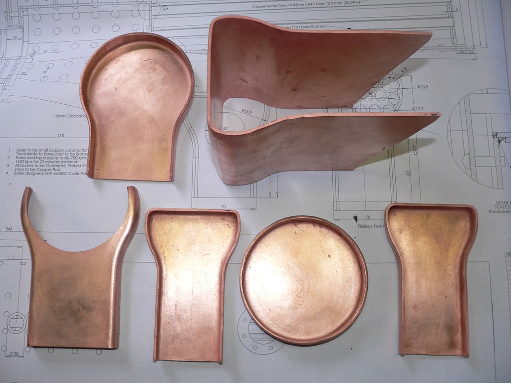
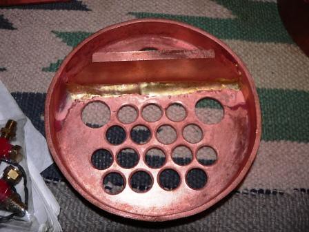
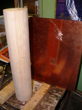
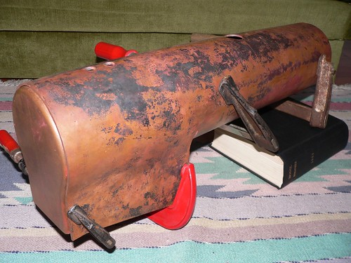
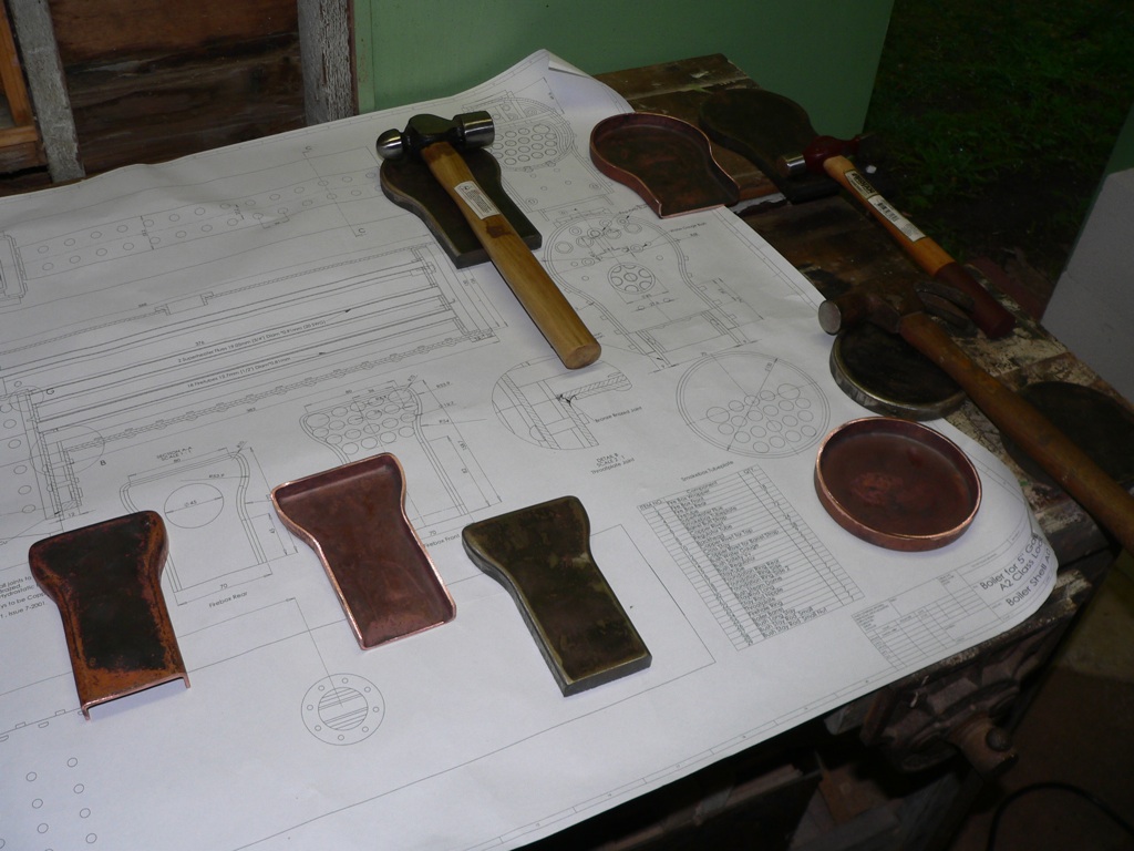
Some of the completed boiler components
More pics to come...
I have been reading the various very interesting threads on this forum and thought I might add what I have been doing...
I have always wanted to build a live steam locomotive and during the final year of my engineering degree, a couple of years ago, I thought I might be able to come up with a boiler design, as the first step and the topic for my final year project.
I took this idea to one of my lecturers and he looked at it and said; "Steve I don't think you should design this.... You should design and build it!"
Without having a specific loco in mind I started with some general external dimensions for a 4-6-0 type 5" gauge loco boiler. From there I conducted some research of current design practices and an extensive heat transfer analysis of various fuels and boiler configurations.
One of the objectives of my project was to come up with a design that was efficient as possible based on the heat transfer 'theory'. As I found out, this requires a number of assumptions and is not straightforward. An excellent book on the subject; Steam, its Generation and Use, Babcock and Wilcox, 1978 states on calculating furnace temperatures;
An analytical solution of the problem of heat transfer in the furnace of a steam generating unit is extremely complex. It is not possible to calculate furnace outlet temperatures by theoretical methods alone. It goes on to list factors to be considered such as furnace geometry, fuel variation, surface variation and load as some of the factors that influence temperature. Also; Temperature varies throughout the furnace. Fuel and air enter at relatively low temperatures, reach a high temperature during combustion, and cool again as the products of combustion give up heat to the furnace enclosure. All temperatures change with load, excess air, burner adjustment and other operating conditions.
Based on a theoretical load, the completed design would need to produce 10.5kg of steam per hour, at 700 kPa which would require 7.7 kW of energy input. In order to do this efficiently a Firebox with as large a surface area as possible was incorporated. 18 Firetubes were included of 11.1mm ID (Inside Diameter). This was slightly larger than the optimum diameter for heat transfer in order to allow for soot build up and cleaning.
Analysis of the draft design was based on an optimum theoretical efficiency of 82%. This equates to the burning of 1.027kg of Bituminous Coal per hour and an energy input rate of 9.38 kW. Based on these figures the calculated theoretical efficiency was found to be 91.5%. With the aid of these results a detailed design was prepared in CAD. The draft design was developed IAW the AMSBC (Australian Miniature Boiler Safety Committee) Code for copper boilers and in consultation with a certified boiler inspector.
Theoretical and Computational Stress Analysis of the boiler design were calculated and amendments to the design were made as required. The Maximum Shear Stress (Tresca Stress) was found to be 15.87 MPa and the Factors of Safety were calculated for the Boiler and found to be 2.65 against Yielding and 7.1 against Ultimate failure.
With the design approved material and tools were purchased and construction began with the Waterjet cutting of all copper plate and Laser cutting of 16mm mild steel Formers. All of the boiler plate was formed to shape and the Barrel rolled to the correct diameter. The Butt Strap was Silver Brazed to the Barrel. The Throatplate was fitted with a combination of Bronze and Silver Brazing. All the Boiler Bushes and the components for the Boiler and Regulator were machined to size. The Inner Assembly was completed, passed inspection and fitted into the Barrel.
So over 12 months I embarked on a very steep learning curve that started out as a blank sheet of paper and ended up with a successful hydro test...! As you can see the boiler I ended up with, is not to dissimilar to many standard designs. For the construction the book; "Model Locomotive Boilermaking" by Alec Farmer was always close at hand in the shed and highly recommended.
I had never built anything like this before and it was a real challenge and a very valuable learning experience. For those considering it, have a go, working with copper is great fun.
Here are some images....
This is the final design, completed with Solidworks 2006
Here are the boiler components being profile cut on a Waterjet machine
Forming the firebox tubelplate. This required annealing 5-6 times from memory.
Some of the completed boiler components
More pics to come...
")