- Joined
- Aug 25, 2007
- Messages
- 3,890
- Reaction score
- 715
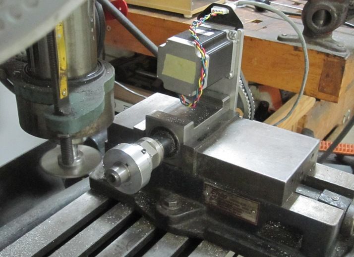
This is a (much) larger 4th Axis I've started putting together. I already had the parts on hand so thought I'd see what I could do. The stepper is a NEMA 34, 1600 Oz In rated at 3.5 amps. It won't go very fast, but it does have some fearsome torque!
[ame="https://www.youtube.com/watch?v=1YeG42yBHwo"]https://www.youtube.com/watch?v=1YeG42yBHwo[/ame]
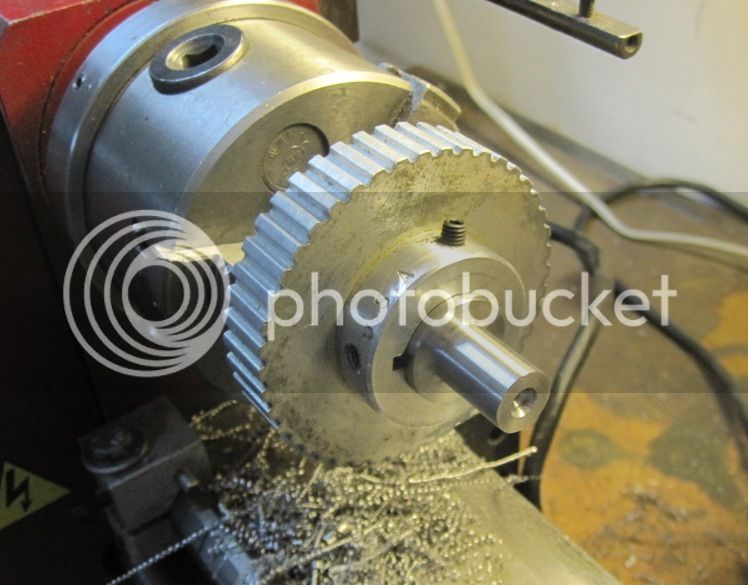
The spindle assembly comes from a dividing head I had made a number of years ago. I replaced the 40 tooth worm gear on the back with a 44 tooth timing pulley which is keyed and setscrewed to the shaft. The spindle itself came from an Atlas 6" lathe and has a 1 inch x 10 TPI thread. It runs in Timken tapered roller bearings on both ends. The chuck is a 4", 3 jaw which I've added a ring with set screws to so I can adjust the run-out to near zero.
The motor is hooked up to a Gecko G540 controller powered by a 24v, 15 amp power supply. I'm thinking a 48v supply might be better so will be on the lookout for one of those. Next I'll figure out how to put this all together in a permanent assembly that I can use with my mill / drill.
Chuck
[ame="https://www.youtube.com/watch?v=1YeG42yBHwo"]https://www.youtube.com/watch?v=1YeG42yBHwo[/ame]
The spindle assembly comes from a dividing head I had made a number of years ago. I replaced the 40 tooth worm gear on the back with a 44 tooth timing pulley which is keyed and setscrewed to the shaft. The spindle itself came from an Atlas 6" lathe and has a 1 inch x 10 TPI thread. It runs in Timken tapered roller bearings on both ends. The chuck is a 4", 3 jaw which I've added a ring with set screws to so I can adjust the run-out to near zero.
The motor is hooked up to a Gecko G540 controller powered by a 24v, 15 amp power supply. I'm thinking a 48v supply might be better so will be on the lookout for one of those. Next I'll figure out how to put this all together in a permanent assembly that I can use with my mill / drill.
Chuck