Model steam tram locomotive.

Home Model Engine Machinist Forum

Help Support Home Model Engine Machinist Forum:

This site may earn a commission from merchant affiliate links, including eBay, Amazon, and others.

Tony Bird

Senior Member
Joined
Feb 20, 2011
Messages
822
Reaction score
895
Location
Cardiff, South Wales, UK
Hi,

I mostly make and play with 16MM Scale model steam locomotives that run on garden railways. Most of my stock is scratch built but very occasionally I buy some thing to play with. This happened at this years 16MM NGM AGM I bought a Mamod locomotive and two carriages. The locomotive and on of the carriages was modified into a 'stand off' scale model of a Lagos Steam Tramway locomotive.

As the remaining carriage was rusting under its paint work it was intended to repaint it to match the Lagos tram's carriage. The carriage was taken apart by drilling out 30 + 'pop' rivets and after removing the paint it was decided to try and make the carriage into a locomotive. To allow the carriage to be taken apart during construction shouldered nuts were soldered into the 'pop' rivet holes. The carriage ends and sides were cut away. The assembled carriage body was painted and lining tape applied.

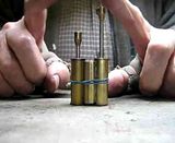
Thoughts were given to a suitable boiler and it was found that one of the boilers made for a model boat could be shoe horned into the carriage body. The construction of these boilers was described in the Boiler Section titled 'Simple boilers'.

With the boiler fitted within the carriage now tram body thoughts were given to how and where an engine could be fitted. This will be described in my next post.

Regards Tony.

001 IMG_6782 LR.JPG


010 IMG_6712 LR.JPG


IMG_7781 LR.JPG


002 Tram Engine LR.JPG


014 Tram Engine LR.JPG


016 Tram Engine LR.JPG


018 LR.JPG


023 LR.JPG


025 LR.JPG


030 LR .JPG


034 LR.JPG
 
Hi Peter,

Very nice I'm building your Aderyn steam motor at the moment, going well.

Good luck with your build. I had thought of using a slightly larger version of the ASM in the Tram locomotive but I had some Mamod locomotive cylinders. The 4 pairs of cylinders that I have had been bought for a very reasonable amount at a model toy exhibition.

The cylinders were all very mucky and one was cracked and had one of its covers missing. It was decided to see if a pair of these cylinders could be used on the tram locomotive. The first job was to take them apart. The cylinder covers are a push fit. The top cover was the first to be removed by putting a rod though the big end hole and hitting the big end with a hammer, the piston then pushed the cover out of the cylinder. A punch and die was made to remove the lower cover in a similar manner. With the cylinders apart they were cleaned and their bores lapped.

I will continue in another posting.

Regards Tony.

016 IMG_6865 LR.JPG


005 IMG_6873 LR.JPG


006 IMG_6875 LR.JPG


007 IMG_6876 LR.JPG


017 IMG_6912 LR.JPG


007 IMG_6886 LR.JPG


008 IMG_6887 LR.JPG


009 IMG_6888 LR.JPG
 
Tony, I didn't realise that the cylinder end covers were made just a push fit. I thought they would be at least soldered.

John
 
Hi John,

I didn't realise that the cylinder end covers were made just a push fit. I thought they would be at least soldered.

Certainly all the older Mamods which are the only ones I have worked on, the cylinder covers are an interference fit in the cylinders. And sometimes maybe to much interference, a fatigue cranked cylinder which might have been caused by a too tight cylinder cover?

Regards Tony.

033 IMG_6956 LR.JPG
 
Hello again,

To continue with the cylinder modifications. Working on previous Mamod cylinders after taking them apart '0' rings have been fitted to their pistons. The Mamod pistons in their locomotives are not rigidly fixed but held in place by a riveted piston rod end acting on a washer on top of an '0' ring which allows the piston to rotate on its rod. Also it allows a certain amount of compliance if the bore isn't concentric with the hole in the cylinder cover. So when fitting '0' rings a new piston was made and rigidly fitted to its rod and often a new cylinder cover was fitted that had a gland sealing the piston rod.

I wondered if it was possible to fit an '0' ring to an original 'loose' piston. A runner was made to allow the pistons big end to rotate in the tail stock of the lathe. The cylinder cover was held out of the way using masking tape and the piston was held in a collet. An off-set 'T' rest was made and bolted to the cross-slide and the slot for the '0' ring was hand turned in the piston. All the slots were successful except for one where the recess for the '0' hold the piston was deeper. The rear cylinder cover was replaced using a hollow punch and a hammer.

Next post cylinder port block and reverser/throttle valve.

Regards Tony.

057 LR.JPG


010 IMG_6889 LR.JPG


011 IMG_6891 LR.JPG


012 IMG_6892 LR.JPG


027 IMG_6935 LR.JPG


015 IMG_6894 LR.JPG


034 IMG_6963 LR.JPG


032 IMG_6955 LR.JPG
 
If you are interested in garden tramways, have a look at this blogspot: http://trevs-tramway.blogspot.com.au/

Trevor is a wonderful model maker and his blog is worth a detailed look. The steam tram is a beauty - electric traction with coal flavoured steam.

The trams run from a terminus at The Rock, to another at Hard Place via Memory Lane. The detail is amazing.

Of course he is a ratbag (that's Oz for eccentric) but aren't we all?

Jim
 
Hi Jim,

A very interesting link. Thank you.

Hi Dave,

Thank you for the compliment.

Hi.

Mamod cylinders as made have a lot of lap on the valves and the engines tend to run smoother if there is very little. This was done by increasing the size of the three ports until the port in the cylinder nearly touches the edges of the two ports in the port block. The mating port faces of the cylinder and port block are lapped on a fine wet and dry paper which is on a sheet of glass. It doesn't need to be a polish finish just flat! The spring tension on the trunnion spring is increased by intoducing washers which also have been smoothed out. When assembled a check is made whether the ports in the cylinder and port block line up, when the best position if any is found, the mating cylinder and its port block is marked so they can go always go together the same way around.

A test of a pair of cylinders with '0' rings fitted.


Reversing/regulator valve next.

Regards Tony.

003 IMG_6812 LR.JPG


020 IMG_6913 LR.JPG


021 IMG_6909 LR.JPG


022 IMG_6910 LR.JPG


023 IMG_6911 LR.JPG


025 IMG_6915 LR.JPG
 
Hi,

The following has no direct application to the tram locomotive being built but might be of interest to those trying to improve the performance of Mamod locomotives.

The reversing/throttle valve.

On a Mamod locomotive the reversing/throttle valve also serves the front frame stretcher the steam passing through the frames to the cylinder. Often the joint between the valve block and the frames isn't very good and steam escapes and can effect the performance of the burner. Like the cylinders the working parts of the reversing valve can be improved by rubbing on wet and dry paper which is on a flat surface. The joint between the valve block and the frames can be improved by using a silicon sealant and improved even more by fitting tubes into the reversing block that go into the frames. If the reversing valve is soldered together excess solder in the valve can be removed to improve the steam flow. Like the cylinders the tension on the spring of the valve can also be increased.

The Mamod locomotive is a wet steamer and can throw out quite a lot water via its chimney this can be reduced by using its smoke box as a water separator. A hole is drilled in the bottom of the smoke box to allow the condensed water out. A silicon tube is arranged to direct the exhaust stem up the chimney at he end of tube is a sealed brass tube with a hole in its side that directs the exhaust to the side of the chimney and the condensing water goes down and the steam up.

The above modifications can improve the performance and control ability of a Mamod locomotive. There are other modifications that can be done to the wheels, boiler and burner to improve a Mamod locomotives performance but are not relevant to this thread.

Regards Tony.

001 IMG_6842 LR.JPG


002 IMG_6856 LR.JPG


003 IMG_6858 LR.JPG


004 IMG_6857 LR.JPG


005 IMG_6863  LR.JPG


007 IMG_6861 LR.JPG


008 IMG_6878 LR.JPG


035 LT LR.JPG


034 LT LR.JPG


036 LT LR.JPG
 
Hello again,

Back to the tram. A lot of thought was given to how to use Mamod cylinders to power the tram ans avoid having to make cylinders from scratch. The cylinders are quite large 3/8" (9.5mm) bore x 3/4" (19mm) the centre distance beween the axle and cylinder trunnion being 1.3/4" (44mm). The carriage frames are 5.1/2" (140mm) long and its axle centres 2.3/8" (60mm). It was hoped to use the original carriage frames but it soon became obvious that they were too far apart so the cylinders would stick out a long way. So new frames would have to be made which in some ways made it easier from s design point of view. Inspiration eventually came from two locomotive manufacturing companies; Ramsome & Rapier who made a 0-4-0 steam locomotive using a jack shaft drive geared to the its leading axle which was connected to the trailing axle via a chain. The other locomotive manufacturer was Breda who made some of its 0-4-0 tank engines with their outside cylinders mounted between their axles.

So this is what I came up with.

Regards Tony.

058 LR.JPG


059 LR.JPG


063 LR.JPG


069  LR.JPG
 
Hi,

A video taken yesterday of the chassis's first steam test.


Considering the small balanced flywheels and light aluminium wheels it runs quite smoothly. I still have to figure out where to put the regulator, reversing valve, lubricator along with their relevant pipe work. The next will be safety valves which I have to make a number of, for this and other boilers.

Regards Tony.
 
Hi

The plumbing has been started and the model run for the first time under its own power.


Some plumbing left to finish and a lubricator to make.

Regards Tony.

075 LR.JPG


076 LR.JPG


080 LR.JPG
 

Latest posts

Back
Top