ML Midge piston

Home Model Engine Machinist Forum

Help Support Home Model Engine Machinist Forum:

This site may earn a commission from merchant affiliate links, including eBay, Amazon, and others.

jack620

Well-Known Member
Joined
Jan 6, 2013
Messages
322
Reaction score
113
Location
Melbourne, Australia
As soon as my piece of CI arrives in the mail, I want to get started on my pistons. Unless I'm going mad (likely), there is no dimension on the plans for locating the wrist pin hole in the piston (see below). Is there some Golden Rule for locating wrist pins in pistons that I don't know about?
Chris

Screen Shot 2013-01-15 at 9.17.10 AM.png
 
Hi Chris

No you're not (going mad)
That's an important dimension that should be there - any deviation from the original designers intention will have an effect on the timing.

You may have done so already but just check if that info isn't on another drawing. Wrist pin height is usually given from the top of the piston.

Failing that it should be able to be checked back from the GA -assuming there is one
Regards - Ramon
 
From the drawing I would say the center is 2.5 the bottom of the piston which is the reference point for all the dimensions.
 
Ramon,
Thanks. I'll email the person who drew the plans and ask him to amend the plans. I'm not sure what GA is?

Portlandron,
It has to be more than 2.5mm. The piston is 10mm tall. I'd say it is around 4mm going by the scale.
 
:wall: Sorry about possible misleading you - just shows I need to put on my glasses before trying to read the fine print.
 
As soon as my piece of CI arrives in the mail, I want to get started on my pistons. Unless I'm going mad (likely), there is no dimension on the plans for locating the wrist pin hole in the piston (see below). Is there some Golden Rule for locating wrist pins in pistons that I don't know about?
Chris

You should be able to calculate this given rhe throw of the crankshaft, the legnth of the connecting rod ( center to center ) and the position of the piston at BDC or TDC. In fairness all these dimensions should be clearly marked on the original plans. But it seems that some designers wish to play with mental arithmatics with the builders. This would never be tolerated in an industrial enviroment.

A.G
 
GA means "General Arrangement"---The master drawing showing all of the parts and their relationship to each other, with a few overall dimensions and possibly a bill of material.
 
Thanks gents. Now that I know I'm not mad (thanks Ramon) I've sent an email to the person who drew the plans asking for the missing dimension.

Chris
 
5 mm is the dimension shown on the Model Engine News plan set for the Midge. I agree the dimension is missing from the original plans. Someone might argue the centerline through the wrist in hole connotes being centered in the 10-mm piston height, but that's poor practice if that was the intent. The current confusion makes that self-evident.
 
Today I started turning down a 100mm long piece of 30mm diameter CI (smallest I could buy). It's the first time I've ever turned CI and I was surprised how nice it was to turn using my diamond tool holder. It makes a mess though. :eek:

I'm trying to work out the most efficient way of turning up 2 pistons and 2 contra pistons. The CI isn't cheap by the time you add postage and I'd like to have enough left over to make at least one more engine (between 2cc and 5cc next time). So here's what I'm thinking:

1. Turn down enough to make the 4 parts plus an allowance for parting off each part. I'll turn to finish diameter (10mm) plus an allowance for lapping. I think 40mm long should be plenty,
2. Bore out the 'guts' of piston 1 and part off with my fin cutting tool,
3. Repeat for piston 2,
4. Bore CP1 and part off,
5. Repeat for CP2,
6. Drill and ream wrist pin holes (method TBA).

Does this sound feasible?
 
Someone might argue the centerline through the wrist in hole connotes being centered in the 10-mm piston height, but that's poor practice if that was the intent. The current confusion makes that self-evident.

That type of argumentation is IMO foolish, because the horizontal centerlne is extending only a little bit out of the circle. Therefore the centerlines are only indicating the center of the bore, not a symmetry of whole part.

There's another mistake in that drawing: the vertical centerline SHOULD BE extending through the whole part, because this is symmetric !

Mike
 
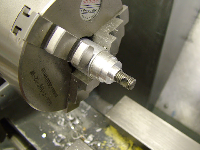
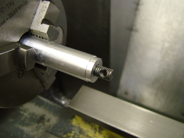
Hi Chris, If you haven't turned too much of your CI stick down you could save on material by this method ... cut off a couple of slices say 12 thick then cut each side of the disc away to give a 30mm long square stick with slighly radiused ends. Pop in the fourjaw and bring to round section as long as possible then reverse it in the three jaw to finish off the square end. With a nice thin parting tool you should easily get a piston and CP from each piece. Yes a bit long winded but it does save material and there will be a hell of a lot less swarf too ;)

Some may question that the 'grain' is in the wrong direction but I have never found this to be a problem. I usually make mine from a cut off of a slab of continuous cast meehanite that I have exactly as above only with slightly more material to play with

Re the making - the method you propose is ok - how are you intending to lap the piston after parting off?

I'm not sure you if you've made it yet but personally I would always make the liner first and lap it before turning the piston - that way you can be sure of leaving the right amount on (the piston) for lapping - not too little and, sometimes worse, far too much.

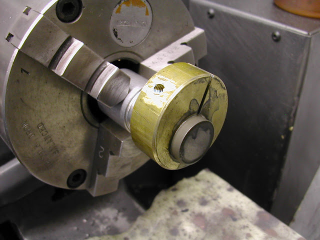
The CP can be a problem to get the right fit. If it is reccessed then I have found the best way to hold it is to push it on to an expanding mandrel which will hold it sufficiently to lap. I have tried this tapered thin wall method recommended by some but so far have had little success with it, much prefering to lap a thicker walled it version to fit. This process was covered on the Super Tigre build.

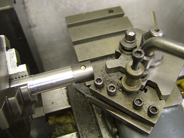
Drilling and reaming the wrist pin holes can be done on the mill - I'm assuming you have one - just hold it in a vise gripping the skirt and top face, set the spindle to the centre line and position from the top face then drill and ream through. If you haven't got a mill then a drill jig is the next best way to ensure the accuracy required, carrying this out before lapping of course.

10mm is quite a small bore - how are you intending to do that in the liner?
Quite often just reaming will leave very shallow undulations in the bore only noticeable when lapping begins so you need to make allowance for that. The other thing to be aware of is the pressure of the jaws if holding the liner itself directly in the three jaw - this too will result in three distinct marks up the bore which will have to be lapped out and the more lapping is done beyond what is neccessary the more the possibilty of bell mouthing/over tapering the bore. By doing the bore first in a fairly substantial piece then holding it on a mandrel to turn the OD's eliminates these potential problems considerably.

Hope this helps

Regards - Ramon
 
Ramon,
thanks for all the good info.

The "grain" problem you mention is the reason why I was going to turn them down, thereby wasting a huge percentage of the stock. I'll have a think about your "slice, trim & turn" method.

I am planning to lap the piston by holding it on an expanding mandrel inside the piston. I hope to do the CP the same way.

I haven't made the liner yet, and I am planning to make it first. At this stage I am just turning the CI piston stock down to slightly oversize.

I don't have a dedicated mil, but I do have a milling attachment for my lathe (see pic). Finding the dead centre of a round part (in this case the piston) is something I have yet to master.

Finally, today I made a boring bar holder to take 6mm round HSS. I ground a boring bar using the info from Harold Hall's website. I've only tested it on a piece of Delrin, but it seemed to work well. I'm pretty sure it will do a 10mm bore. I will do as you suggest and bore it with thick walls then turn the OD on a mandrel.

Chris

IMG_20130113_132421.jpg
 
Ramon,
thanks for all the good info.

The "grain" problem you mention is the reason why I was going to turn them down, thereby wasting a huge percentage of the stock. I'll have a think about your "slice, trim & turn" method.

I am planning to lap the piston by holding it on an expanding mandrel inside the piston. I hope to do the CP the same way.

I haven't made the liner yet, and I am planning to make it first. At this stage I am just turning the CI piston stock down to slightly oversize.

I don't have a dedicated mil, but I do have a milling attachment for my lathe (see pic). Finding the dead centre of a round part (in this case the piston) is something I have yet to master.

Finally, today I made a boring bar holder to take 6mm round HSS. I ground a boring bar using the info from Harold Hall's website. I've only tested it on a piece of Delrin, but it seemed to work well. I'm pretty sure it will do a 10mm bore. I will do as you suggest and bore it with thick walls then turn the OD on a mandrel.

Chris

Hi Chris,

To find the dead center of the piston is not difficult but a bit fiddly and time consuming in your set up. I for one would try to machine the piston on the chuck and then bore it using a very small boring bar to size, you can then reverse it in the chuck and part it to length as a little bit of run out during the parting should not interfere with the op, all this is applicable if the hole is round and not ablong. Make sure that you do all the cross drillg required before parting while you have some length to play with. If for some reason ( the hole being ablong ) you need to bore as per your set up photo then you need the use of a wobble bar and a dti. a very small prick punch mark is required while the piston is in the chuckon the head stock, best done with the smallest center drill that you have and a very light impression not a hole, you'd then remove the piece and true it up in the vice or mount the chuck on the milling slide if possible, and proceed to center it using a wobble bar and the dti as per normal practice.

I am sorry if you already knew what to do.

Regards,

A.G
 
Hi Chris - this is just the way I started out - with just a vertical slide as you have. Not the best of kit compared to a mill but better than nothing at all thats for sure.

Here's another alternative method - Providing your piston is finished to length (OD is not important at this stage - see below)) you can hold it in the vise with the top of the piston against the fixed jaw but first just put a stub of something in the chuck and turn it to 10.0 dia. Then bring your fixed vise jaw up to that and set the slide. That jaw is now 5mm from the axis.

Set something in your drill chuck around 5mm dia - piece of silver steel is ideal and with it rotating bring it up to the piston until you can just feel it nipping a cigarette paper. Set your cross slide dial then move over half the dia of your piston blank and half the dia of the silver steel. You'll be more than near enough to worry about it.

A 10mm piston is getting a bit small for the method I use for holding but you should be able to make a simple fixture for this op. (After experiencing distortion after milling I always turn and lap the piston OD in one hanging on such a fixture) I'd be a bit wary of using an expanding mandrel at this size as it would be very easy to stress the thin wall of the piston outwards which will then affect the lapping - you are talking about some very fine tolerances at this size - the slightest amount under rsize and the fit needed will swiftly disappear.

If you do manage to take it undersize don't despair however as you may be able to save it but let that situation arise first before worrying about it. More on that if you end up needing it

I really wouldn't worry about the grain issue for something like this - it's not as if it's going to be worked at really high stress levels like in a racing or speed engine environment. Your biggest challenge is getting that fit 'one to the other'.

Good luck - I'll keep watching with interest.

Regards - Ramon
 
A.G.
the hole in the bottom of the Midge piston is round, so I will bore it held in the 3 jaw or an ER collet. I was thinking of drilling and reaming the wrist pin holes in my milling attachment simply because my lathe spindle has much less runout than my pedestal drill and also because it is easier to make accurate adjustments on the lathe.

Ramon,
thanks for the tips on finding vertical and horizontal centre. I especially like the idea of using a 10mm stub to set the milling chuck height- very elegant.
I think I may have missed your technique for holding the piston. I thought everyone just used an expanding mandrel in the base of the piston. I can see your point about the expanding mandrel stretching the piston skirt and ruining the fit. Would you be kind enough to elaborate on your method of holding the piston? Sorry if you've already covered it- I'm starting to become overwhelmed with info!

Chris
 
Hi Chris, The fixture for holding pistons is quite simple to make.

A short stub of material - mine are ali and threaded right through to take a threaded rod the diameter of which will take a cross hole to take a pin a little smaller tha the wrist pin. In your case say a 2mm hole through a 4-5mm rod. The stub OD is turned to just smaller than the piston diameter then a short shoulder turned to take the inside dia of the piston skirt. The piston is attached to the rod using a small pin through the wrist pin holes then it is screwed back to the fixture the piston registering over the shoulder. Any turning/lapping forces means it is self tightening and providing the register is good it can be removed and replaced without deviation. Usually, wrapping a piece of 1200 grit wet and dry paper around it is sufficient to apply enough force to loosen it without damage. If the forces tighten the piston such that you can't remove it by hand then the fixture is taken out of the chuck and the screw backed off releasing it easily but this of course destroys the setting - not that important once lapping begins - but that said its not good to lap if it's running eccentrically.

Using a pin smaller than the wrist pin diameter helps lessen any influence if the cross hole is not perfectly in line.

Here are a few pics which should help too

DSCF0795.JPG


DSCF0798.JPG


DSCF0799.JPG


DSCN3127.JPG


The first three are from this thread which you may find of helphttp://www.homemodelenginemachinist.com/f31/super-tigre-g32-1cc-diesel-5cc-version-17674/

The last image is the lapping of an Eta piston using the same type of fixture.

Regards -Ramon
 
Hi Chris , Just a point in case you are unaware ...

If you are going to use diamond paste for lapping you do need to clean the parts in an ultrasonic cleaner before fitting the piston. Reason for this is that diamond particles will embed themselves into the soft material and will not release completely with conventional cleaning in solvents /scrubbing etc.

As you can imagine if this is allowed to happen the piston laps itself in pretty quickly on first running and very quickly out again too :eek:

Using silicon carbide - carborundum - and cleaning in cellulose thinner prevents this situation ;)

Apologies for teaching granny if you knew this already

regards - Ramon
 

Latest posts

Back
Top