Millie steam engine & video

Home Model Engine Machinist Forum

Help Support Home Model Engine Machinist Forum:

This site may earn a commission from merchant affiliate links, including eBay, Amazon, and others.

ChooChooMike

Well-Known Member
Joined
Jan 5, 2008
Messages
864
Reaction score
13
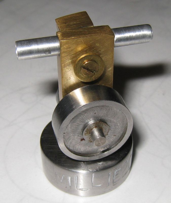
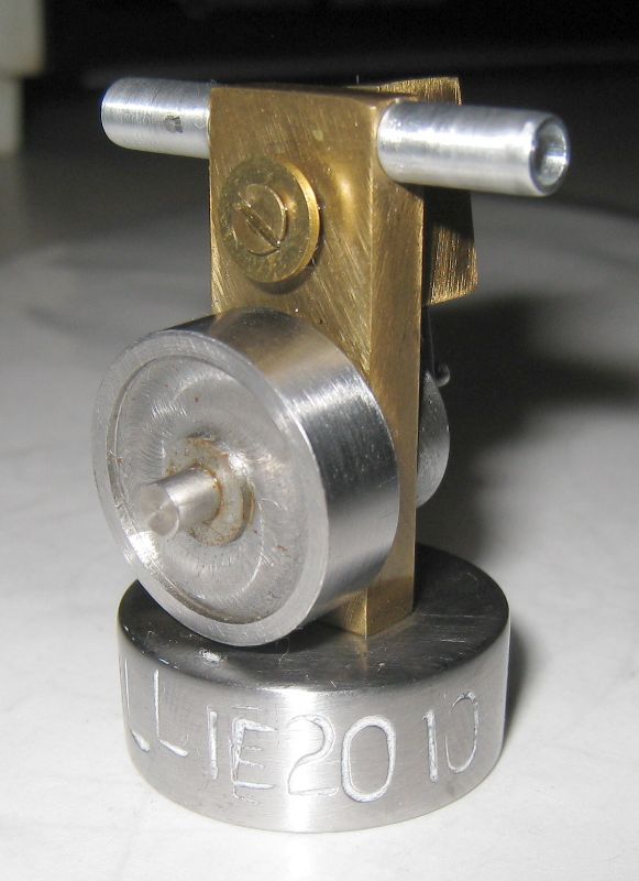
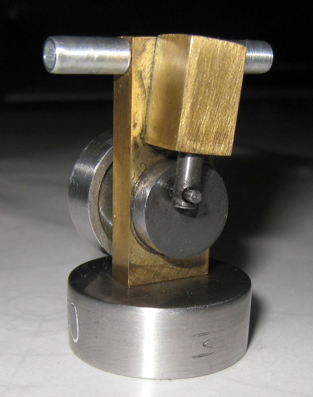
Here's my version of "Millie" that I finished a couple of months ago.

Millie is a single-acting oscillator or "wobbler" engine. Runs like a champ in either direction using about 10-15psi from a small paint brush compressor. The frame is 1-1/4" high, flywheel is 3/4" diameter, pistion is 1/8" diameter with a stroke of about 1/4". Made of brass/steel with aluminum for the tubing nipples.

This is my 5th running engine, if you count my finger powered one :D This is the 1st that I built entirely on my Sherline mill and lathe at home. Perfect size equipment for this engine. The rest were 97.4% built on conventional sized equipment in my shop classes over the past few years.

This was a great build for me, complete with a number of screwups (who hasn't !) and a great experience in learning to use my Sherlines. Yup, I've got tons of pix along the way and will post build thread.

Plans from Sherline's Tabletop Machining book - originally published in Modeltec, May 1997.

Mike

Listen for the "revving" sound !! :big:

[ame]http://www.youtube.com/watch?v=VCgqIxOxoZo[/ame]

[ame]http://www.youtube.com/watch?v=QQNhOfvQ8hU[/ame]

[ame]http://www.youtube.com/watch?v=MFYT8ULMPB4[/ame]

The engine looks a little rough and acquired some "patina" ... ok a tad bit of rust from sitting around. I have most of the tooling marks sanded out, but I gotta git out the Dremel and clean up some of the gunk (oil/dirt), especially on the flywheel. I had Millie running on my paintbrush compressor for over an hour at one point just for kicks !! My very poor attempt at hand stamping "Millie" on the base turned out pretty bad, gotta laugh about it now !!
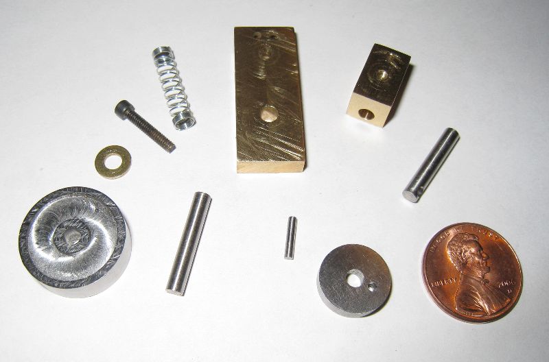
millie01.jpg


millie02.jpg


millie03.jpg


The parts :

millie04.jpg


11/12/11 Edit: added 2 more short videos I found laying around.
 
Nice job Mike...great pictures and video too......so what is #6 going to be ??

Bill
 
Thanks Bill. I already started on Little Machine Shop's wobbler. I bought the plans/DVD/materials kit a few years ago. Figured I'd knock that one out and get some more time/experience on the Sherlines before doing something more complicated. :) Practice some boring, making a brass bushing for the axle and some fixturing techniques.

I've been wanting to build Elmer's "Tiny" for the last few years too. It's a little bit smaller then "Millie".


Mike
 
Awesome Mike! I'm a big fan of small wobblers. :bow:

Those engines are a blast to run, and boy does yours run good. sounds like a lot of 'mouse' power in a small package.

I just love it!

-MB
 
Neat build Mike and great video. :bow: I didn't realize how small it was until I read the specs and saw your hand flip the flywheel at the start of the video.

Cheers,
Phil
 
Nice Build Mike! Thm:

Those little ones do like to dance around.

Rick
 
Metal Butcher said:
Awesome Mike! I'm a big fan of small wobblers. :bow:

Those engines are a blast to run, and boy does yours run good. sounds like a lot of 'mouse' power in a small package.

I just love it!

-MB

Thanks MB, means a lot coming you, I've seen your engine collection :bow: !! Yeah, I like the revving sound, neat side effect !! "mouse power" LOL :big: I like that !!

rake60 said:
Nice Build Mike! Thm:

Those little ones do like to dance around.

Rick

Yes, they do. IIRC, your "Tiny" sounded like a wasp buzzed around !! Definitely had a little trouble holding it down for the video. Guess I shoulda clamped it in something :)

Philjoe5 said:
Neat build Mike and great video. :bow: I didn't realize how small it was until I read the specs and saw your hand flip the flywheel at the start of the video.

Cheers,
Phil

Thanks Phil - yup, it's just a little bigger then Elmer's "Tiny" - that's on my list to build too !!

Mike
 
Hi Mike,

Pardon me for bring up an old thread of yours. I'm building the Millie and am left with the Cylindar. Quite a few mistakes along the way. Will know if they fit together during assembly.

You mentioned in the first post that you've pics of your build. Do you still have them? I'm rather new to this and was figuring out along the way how things can be done (or should be done).

One other question: from the article supplied with the kit (from Sherline), the author mentioned that putting in a square stock in a 3 jaw will naturally offset the bore that is to be done. I faced the 2 sides on the lathe with the 3 jaw to see where the center will end up. Saw from both sides that I'm not able to get to the center to the location called out in the plan. Did you use a lathe to bore the hole as suggested or the mill did the job for you?

Regards,
Wong

p/s: my struggle can be found here: www.wongstersproduction.blogspot.com
 
Wow, millie was the first engine that I made with my Sherline mill and lathe. It took quite a while at that time to make all the parts, including starting over on a couple goofed up parts. I've been thinking of making a few more for Christmas stocking suffers.

Anyway, I would suggest using a mill if you have access to one when making the cylinder. When I made millie, I used the mill for all the square parts, including drilling all the holes in the square parts, and used the lathe for all the round parts.

By the way, that's a nice blog you've posted on making millie.

Russ

[edit] I just noticed, on your blog, it looks like you counterbored the cylinder mount on the same side as the cylinder ports. That was one of the mistakes that I made. I ended up machining another cylinder mount to get the counterbore for the spring on the side opposite from the cylinder ports.

I spent about 6 hours machining a jig for grinding 1/8" x 1/8" high speed steel bits to a 60 degree point. I was so proud of myself. The finish was nice, the dimensions were spot on...opps, that was supposted to be 30 degrees, not 15! I'm thinking of mounting my jig for 30 degree bit points on the wall to remind me to be sure of the angles before machining. Oh well, water under the bridge. [end edit]

Millie[1].jpg
 
Russel said:
[edit] I just noticed, on your blog, it looks like you counterbored the cylinder mount on the same side as the cylinder ports. That was one of the mistakes that I made. I ended up machining another cylinder mount to get the counterbore for the spring on the side opposite from the cylinder ports.
[end edit]

Hi Russel,

Thanks for your comment. About the counterbore being on one side or the other, isn't it the same? I hope I didn't get this part totally wrong. I thought all the holes on the "face" of this part are through holes...

Regards,
Wong

Edit: I think I know what you meant, Russel. I went back to Mike's 3rd pic and saw that the 2 1/16" holes didn't appear at the back. So they're not through holes. Sigh... May I know how to tell from the plan that they're not through holes? Nothing denotes that on the plan. Maybe its in the text which I missed... Now that I know, may I know how deep I should drill the 2 1/16" holes to allowing the 1/8" holes from the 2 sides (inlet and outlet?) to just break through? Thanks for pointing out my mistake.
 
Keep at it. I'm looking forward to seeing your completed millie.
 
wongster said:
Hi Mike,

Pardon me for bring up an old thread of yours. I'm building the Millie and am left with the Cylindar. Quite a few mistakes along the way. Will know if they fit together during assembly.

Hey Wong - I see you found me here after your YouTube comment ! This is a nice place to hang out ! Great buncha folks and TONS of machining knowledge & tips :)

You mentioned in the first post that you've pics of your build. Do you still have them? I'm rather new to this and was figuring out along the way how things can be done (or should be done).

Yes, I'll have to dig them up. Been meaning to post a build log (mistakes and all) since last year, time escape me lately :p

One other question: from the article supplied with the kit (from Sherline), the author mentioned that putting in a square stock in a 3 jaw will naturally offset the bore that is to be done. I faced the 2 sides on the lathe with the 3 jaw to see where the center will end up. Saw from both sides that I'm not able to get to the center to the location called out in the plan. Did you use a lathe to bore the hole as suggested or the mill did the job for you?

Russel said:
Anyway, I would suggest using a mill if you have access to one when making the cylinder. When I made millie, I used the mill for all the square parts, including drilling all the holes in the square parts, and used the lathe for all the round parts.

Like Russel said, I too did the all the square parts/drilling on the mill. I do remember that tip about the 3-jaw, but using the mill made more sense.

p/s: my struggle can be found here: www.wongstersproduction.blogspot.com

Nice build pix too.

[edit] I just noticed, on your blog, it looks like you counterbored the cylinder mount on the same side as the cylinder ports. That was one of the mistakes that I made. I ended up machining another cylinder mount to get the counterbore for the spring on the side opposite from the cylinder ports.

s_750.jpg


As noted, the cylinder pivot counterbore is on the opposite side from the valve holes/ports. That's indicated by the dashed circle on the cylinder mount drawing. (incorrectly pictured here).

About the counterbore being on one side or the other, isn't it the same? I hope I didn't get this part totally wrong. I thought all the holes on the "face" of this part are through holes...

The counterbore on the opposite side from the ports is to help retain the spring.

I think I know what you meant, Russel. I went back to Mike's 3rd pic and saw that the 2 1/16" holes didn't appear at the back. So they're not through holes. Sigh... May I know how to tell from the plan that they're not through holes? Nothing denotes that on the plan. Maybe its in the text which I missed... Now that I know, may I know how deep I should drill the 2 1/16" holes to allowing the 1/8" holes from the 2 sides (inlet and outlet?) to just break through? Thanks for pointing out my mistake.

s_753.jpg


The cylinder port holes do NOT go all the way through. I don't remember if that was specified on the drawing. They should only go deep enough to intersect the port inlet holes.

Similar on the cylinder:

s_754.jpg


The port hole should only go deep enough to intersect (i.e. break into) the cylinder. I vaguely remember making the cylinder 2X since I had drilled the port hold on the wrong side of the cylinder :p Remember when drilling holes to a given depth, you have to account for the angle of the drill tip and adjust the depth accordingly.

Another tip is the port hole needs to be deburred on the inside of the cylinder. If you drill the port hole after drilling the cylinder hole, there'll be a burr on the inside of the cylinder from where the port hole breaks through.

A clever way around that is to drill the port hole 1st, then the cylinder hole - there'll be no burr on the inside that way.

Other things I remember

1) in my case I had to do a LOT of fiddling with the parts to get the engine to run smoothly. I assembled everything, then found out the piston was hitting the top inside of the cylinder causing it to bind. Solution - shorten the piston a tiny bit till it fit with no binding.

2) there was a lot of other stuff binding - flywheel against the cylinder mount, and crank disk against the cylinder mount. Solution - I put a small washer between the flywheel and the mount. That kept the flywheel from rubbing against the mount. I don't think I needed a washer between the crank and mount after that.

3) cylinder wasn't wobbling very freely against the mount - solution - adjust the spring tension till it ran more freely. That involved snipping the spring off until these was less pressure.

Trust me, I made all kinds of mistakes, and was actually a bit challenging ! I did the flywheel counterbore on the mill/rotary table. I wound up using Super glue to hold it down to a piece of aluminum so I could then clamp it to the rotary table.

I'll try to dig up my pix this weekend and post a build log. Actually learned a whole ton of stuff using my Sherlines with this build Thm:

Mike

Size comparisons to full-sized lathe ;D

MillieOnBigLathe01.jpg


MillieOnBigLathe02.jpg
 
Thanks Russel & Mike.

I went through the text and didn't see any mention about the air port holes not being through holes. Guess that's where experience comes in, which I've none so far. I tend to go exactly to what I see from the plan (or attempt to, rather).

I ran out of brass stock that is rectangular or square. Have some round stock but my attempt to make it a rectangular piece failed... Will make another attempt, otherwise, I'll have to redo the Cylinder Mount next weekend, if I'm not scheduled for duty.

Looking forward to your build log and sorry for the trouble for digging them out.

Regards,
Wong

 
wongster said:
Thanks Russel & Mike.

I went through the text and didn't see any mention about the air port holes not being through holes. Guess that's where experience comes in, which I've none so far. I tend to go exactly to what I see from the plan (or attempt to, rather).

I just looked at the plans from Sherline's Tabletop Machining book. You're right, it doesn't show how deep those port holes should be. I had previously built a another wobbler, so yeah, that helped figure out that those holes just need to intersect with the port tube holes.

Looking forward to your build log and sorry for the trouble for digging them out.

I found all my pictures tonite, thought I had lost them :'( I'll see about getting a few of them up tomorrow.

I added 2 more short videos to the 1st message too. Found them laying around when I dug up the build pix.

Mike
 
Thanks Mike.

I've yet the time to redo the cylinder mount. Hopefully I can start the rebuild this Saturday after my appointment in the morning.

I'm almost done with squaring up a round brass rod. It should provide me with sufficient material with one extra cylinder mount if I screw up again.

Regards,
Wong
 
I had a go today redoing the Cylinder Mount. It was right until the last 2 little 1/16" holes that I screwed up again... :-\ I drilled both through... Wonder what's wrong with me...
 
Back
Top