BobWarfield
Well-Known Member
- Joined
- Dec 27, 2007
- Messages
- 1,151
- Reaction score
- 1
As I'm bumbling along making a backplate for my collet chuck (which I want to use on the Team Build), I playing with several things that are new to me. I thought I would share one here, which is making your own transfer screws.
Transferring hole locations is one of those finicky operations that a budding machinist has to learn. Most of us start out clumsily measuring things with digital calipers and then wondering why they're off by quite a lot. It's hard to measure holes precisely!
Pretty soon we discover transfer punches, which are really cool. Eventually, we have a blind hole and can't use a transfer punch. The answer there is a transfer screw. It has threads on one end and a point on the other. Screw it into the blind hole and voila: you can transfer! I was so pleased when I discovered these that I promptly ordered all the small imperial sizes I like to use. These things are not cheap, but I find I use them pretty often.
Unfortunately, my chuck backplate project requires M10 bolts. Not wanting to spend the money or worse wait for another set of transfer screws to be shipped, I set about making a set. It's quick and easy for anyone to try. Here are a few photos to show what I'm up to:
I started with an M10 bolt and a couple of nuts to protect the threads.
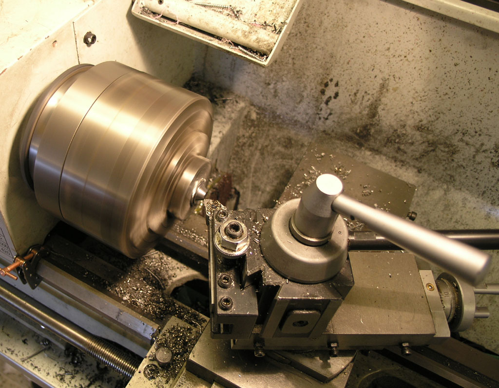
I chucked that assembly in my 6-jaw (a 3-jaw will do), set the compound over for a 60 degree point, and started shaving the head of the bolt. I'm using a 1/2" shank CCMT indexable carbide turning tool for the task.
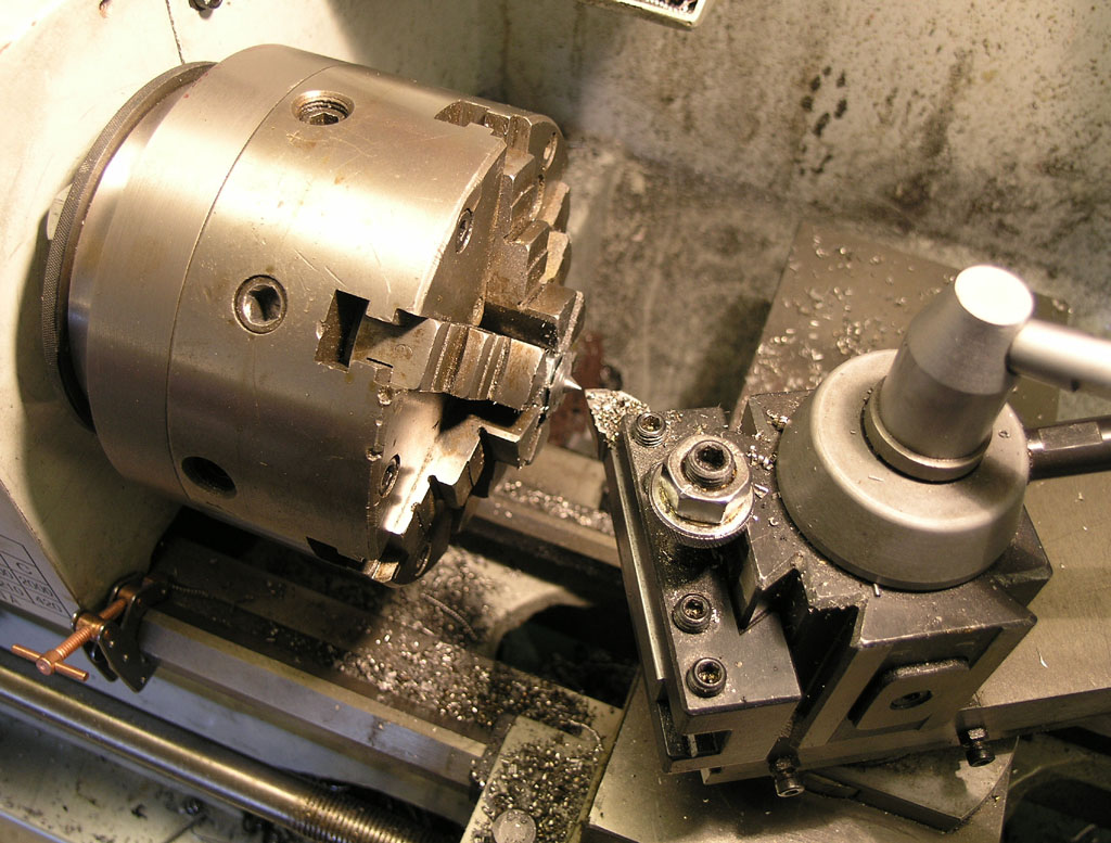
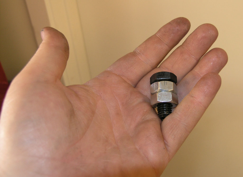
Eventually, you get the nice 60 degree point and you are done.
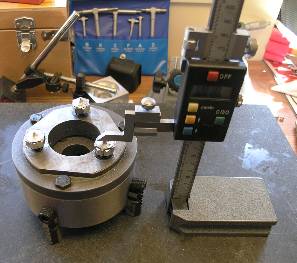
You can see them a little better here. For some unknown obsessive compulsive reason I felt compelled to set all the points to exactly the same height. I must have that obsessive compulsive disease!
<continued>
Transferring hole locations is one of those finicky operations that a budding machinist has to learn. Most of us start out clumsily measuring things with digital calipers and then wondering why they're off by quite a lot. It's hard to measure holes precisely!
Pretty soon we discover transfer punches, which are really cool. Eventually, we have a blind hole and can't use a transfer punch. The answer there is a transfer screw. It has threads on one end and a point on the other. Screw it into the blind hole and voila: you can transfer! I was so pleased when I discovered these that I promptly ordered all the small imperial sizes I like to use. These things are not cheap, but I find I use them pretty often.
Unfortunately, my chuck backplate project requires M10 bolts. Not wanting to spend the money or worse wait for another set of transfer screws to be shipped, I set about making a set. It's quick and easy for anyone to try. Here are a few photos to show what I'm up to:
I started with an M10 bolt and a couple of nuts to protect the threads.
I chucked that assembly in my 6-jaw (a 3-jaw will do), set the compound over for a 60 degree point, and started shaving the head of the bolt. I'm using a 1/2" shank CCMT indexable carbide turning tool for the task.
Eventually, you get the nice 60 degree point and you are done.
You can see them a little better here. For some unknown obsessive compulsive reason I felt compelled to set all the points to exactly the same height. I must have that obsessive compulsive disease!
<continued>