Making a QCTP (Quick change tool post)

Home Model Engine Machinist Forum

Help Support Home Model Engine Machinist Forum:

This site may earn a commission from merchant affiliate links, including eBay, Amazon, and others.
Looking good Phil....Worst parts over....the next tough part is all the tapped holes!...heheheheheheh :big:
 
Thanks Chris and Dave,
steamer said:
the next tough part is all the tapped holes!

On that note, would you recommend using a slightly bigger tap drill on 4140 or just use the recommended size?

Cheers
Phil
 
Hey Phil I can't see why 10mm won't work you don't want to get to big. again excellent work. Cliff
 
4140! Well that explains the endmill wear! ;D

Yes, I would not use the standard 75% depth of thread for 4140, try 50% depth first....and don't even think about using #6...... :big:

Get yourself some EXCELLENT quality HSS two flute spiral gun taps....don't cheap out here with taps if your doing that many holes in 4140....it's not worth it.

Gun taps will push the chip forward and be very free cutting, but you can only take advantage of that with through holes.....like on a tool holder. I think I'd just find a cliff to jump off of if they were all blind holes.. :big:

Dave
 
G'day all,

After cutting up the tool holder blank at work into aproximatly 55mm lengths, I brought them home and set about sqauring them up and reducing the width to 70mm to match the tool post.

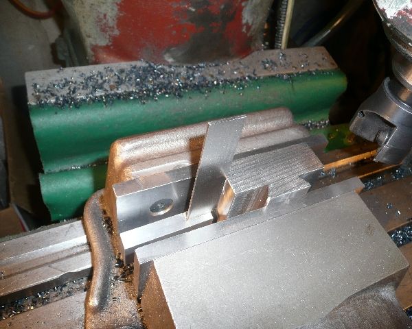
The first operation was reducing the width of the holder. Reference height was taken from the dovetail edge on the moveable jaw of the vice.
Once one side was done, I flipped it over and did the other side. This ensured that the dovetail was central.
All 11 holders were done before moving on to the next operation.

P1070012.jpg


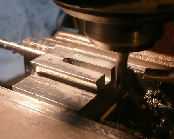
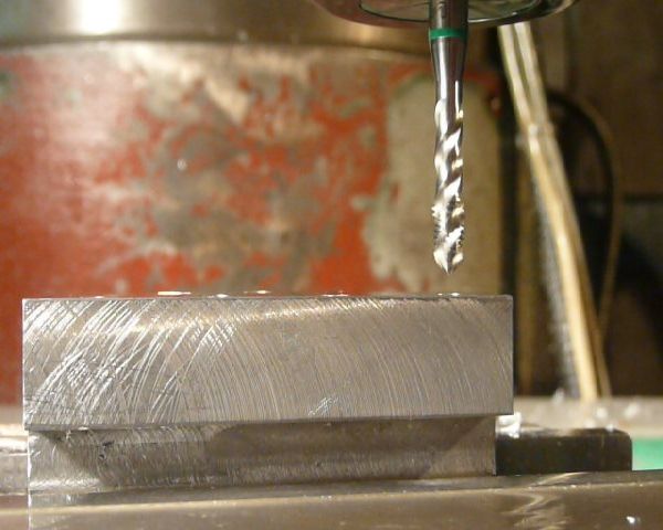
Next was to square up and clean up the adjacent side. Again all 11 were done on one side before flipping them over and milling the final side to size.

P1070015.jpg


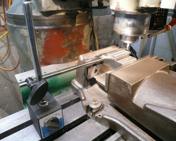
There has been a bit of talk about vice stops and alike, this is what I use as a stop.

P1070017.jpg


Any way, with reference points set in the DRO.
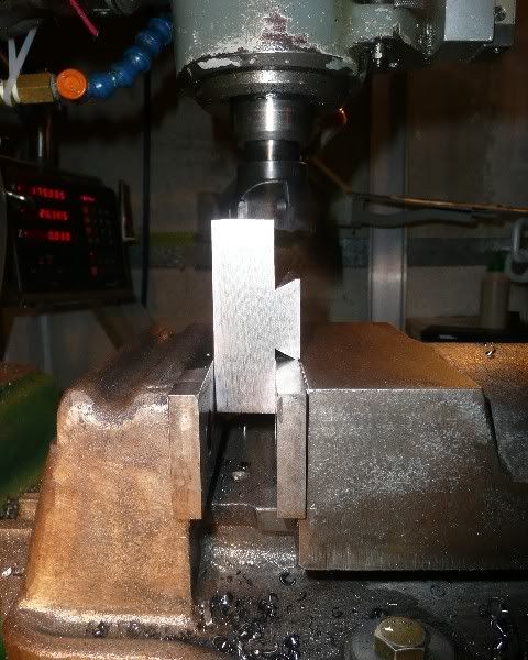
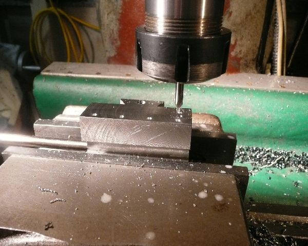
The height adjusting slot was milled using an 8mm universal mill 8mm deep in one pass.

P1070020.jpg


Again all 11 done.

P1070023.jpg


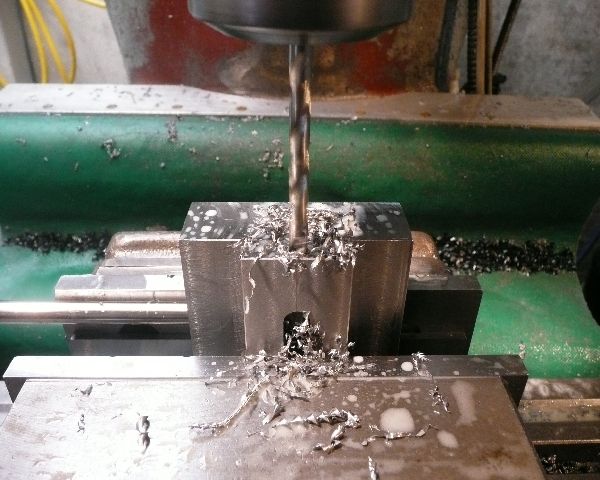
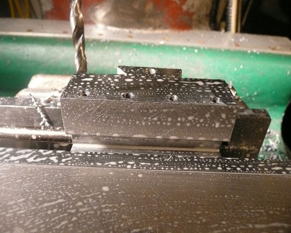
The next job was to drill and tap the height adjusting screw thread. (drawing has M5, I changed it to M6)

steamer said:
Yes, I would not use the standard 75% depth of thread for 4140, try 50% depth first....and don't even think about using #6...... :big:

Get yourself some EXCELLENT quality HSS two flute spiral gun taps....don't cheap out here with taps if your doing that many holes in 4140....it's not worth it.

Gun taps will push the chip forward and be very free cutting, but you can only take advantage of that with through holes.....like on a tool holder. I think I'd just find a cliff to jump off of if they were all blind holes.. :big:

Dave

I took your advice on the depth of tread Dave and used a drill bit for a 50% DOT.
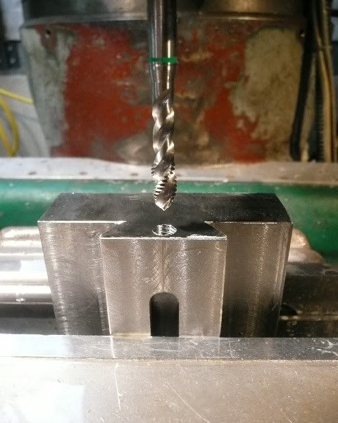
I have a set of Sutton power taps that I used. They draw the swarf out the top as they tap. Good for blind holes as well.
I bought the set when I had to tap 100 blind holes in aluminium. M3 was the size needed but I got the set any way.

P1070026.jpg

P1070028.jpg


That was the last operation that I finished all 11 holders at the same time.
Now it's time to individualise the holders for there intended tools.

When I cutt up the 600mm tool holder blank, the last holder ended up only 40mm high. I started with this one as a test piece.
It will be made to hold 1/4" HSS tooling.

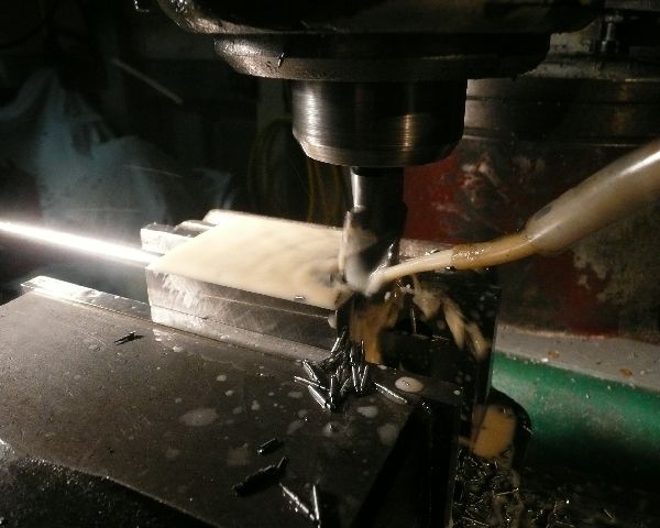
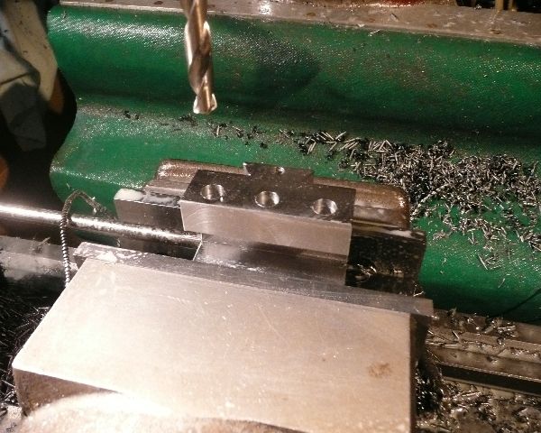
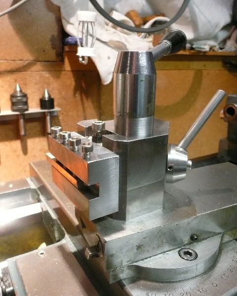
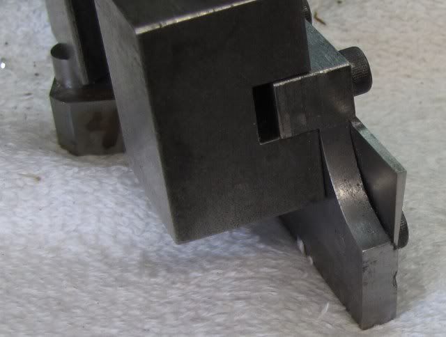
I milled an 8mm wide slot 7mm deep across the holder and then drilled and tapped 4 M5 holes to hold the tool.

P1070031.jpg

P1070032.jpg

P1070033.jpg

[ame]http://www.youtube.com/watch?v=mMU3Q0ovJ2g[/ame]

The tapping is done at 50 rpm and the quill hand feed until the tap bites, then the quill draws itself down and my hand moves to the reverse switch.
When the right depth is reached, I flick the mill into reverse and assist the tap by taking up the weight of the quill with the feed leaver. Again it feeds itself out.
Lots of motion lotion helps (cutting oil)

One down 10 to go. ;D

I did two more holders before I called it quits for the night.
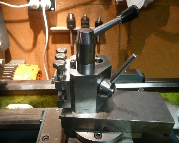
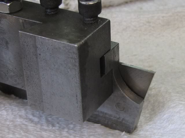
They were some standard holders that can take 16mm tooling. (although I only have 12mm tooling)

Milled a 20mm wide slot 17mm deep in two passes (8mm deep each). Then a couple of clean up passes of 0.1mm on the sides.

P1070035.jpg


Drilled and tapped 3 M10 holes for the tool holding bolts.

P1070039.jpg


Just in case you didn't get bored watching the first tapping movie, here is the M10 being power tapped. :big:

[ame]http://www.youtube.com/watch?v=VSVIPNA0oDo[/ame]
Ah, Not quite as exciting as watching paint dry. th_wav


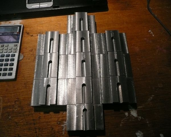
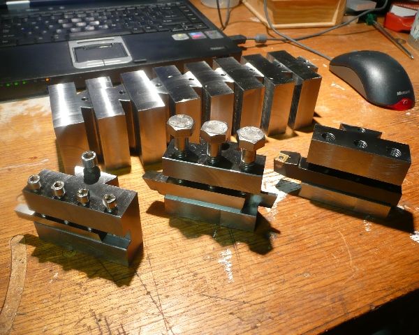
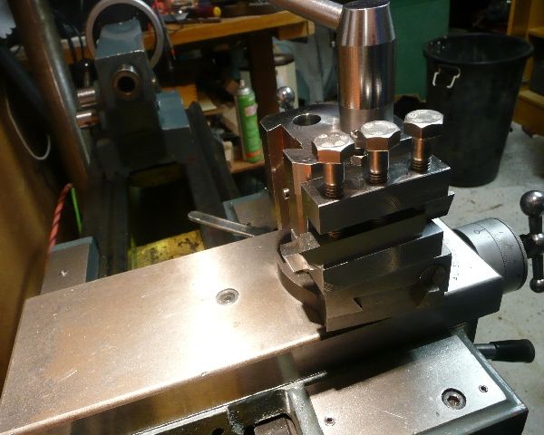
This is the progress so far. The M10 bolts will be changed for cap screws when I get some.

P1070042.jpg


And the same on the tool post.

1/4" tool holder
P1070045.jpg


Standard holder

P1070043.jpg

P1070044.jpg


Well bye for now,
Phil
 
Really very nice Phil :bow:
Regards, Arnold
 

Nice work Phil,

great documentation too!
 
Phil looking real nice. I never had the balls to tap like that be my luck to break the tap right off and ruin the part. Cliff
 
Thanks Arnold, Kustomkb, Dave and Cliff for your kind comments and advice.

Cliff said:
Phil looking real nice. I never had the balls to tap like that be my luck to break the tap right off and ruin the part. Cliff
When I gave the run down on the tapping I should have included this very important bit of information.
When I tighten up the ER32 collet that holds the tap, I just snug it up. That way the tap will slip in the collet and not break. If it slips under normal load, just stop the mill and snug it up a bit more in position.

If anyone has pictures or an explanation on how they made special tool holders it would be greatly appreciated. I'm looking for ideas including parting off holders and boring bars etc.

Cheers,
Phil
 
Hi Phil,

Oh I have GOT to get me one of those taps!......
Of course,neither of my mills have a quil..... :big:

Looking good! Thanks for the video too.....It's really nice to see it done.

Dave

PS hope the cut is healing well......sans alcohol :big:
 
Thanks to all who made comments and gave advice along the way. :bow: :bow:
I'll pop back here to document the making of some non standard tool holders, but that's it for now.

Next project is to cut some missing change gears for the lathe.
This will encompass forming a single point involute tool to fit a fly cutter, and then cutting the gears.
If it hasn't been documented before, I'll spit some pictures out for that one as well.

Then maybe I can get back to Elmer's #24 beam engine that is half done and the boiler to suit.

Kind regards,
Phil

steamer said:
PS hope the cut is healing well......sans alcohol :big:

Thanks Dave, it's a knife like cut under the thumb knuckle. Doing well but not healed yet.
I must remember to keep the alcohol for drinking not washing parts. ;D
Can't say I like the taste of Metho though, and the parts don't come out quite as clean if I use bourbon. scratch.gif
 
Phil,
Here is a cutoff blade tool holder that I made a long time ago.
The support for the blade goes under the blade to keep it rigid as possible. As shown it has a 0.060 blade and will cut off up to 1.25 inches.

The notch for the blade is as snug fit on the blade. It is 0.050 deep at the top of the blade and at the bottom of the blade there is a section about .09 wide that is only 0.033 deep. This keeps the side relief angles equal on both sides of the blade, but if you build one you should probably check your blade as it may be different. In the second photo you can see the small step at the bottom of the blade.

The blade is held in with 10-32 socket head cap screws. On the top of the blade, the blade is thicker than the notch is deep so washers clamp the blade in place. On the bottom, the blade is recessed into the holder, so the 10-32 holes are counter bored so they will clamp on the blade.

Mine is set up with a 0.625 radius support for the 1.25 max cut off diameter.

In use, the blade is indicated in to be perpendicular to the work and with the tip on the center line of the work.

Note the non-active end of the blade has been ground to 0.025 wide for cutting narrow fin slots on small IC engine cylinders. It is easy to reverse or change the blade for such operations.

My tooling is not a nice looking as yours, but it is functional. Thanks for the nice how to thread.

Gail in NM,USA


Cutoff1.jpg


Cutoff2.jpg


Cutoff3.jpg
 
Thanks Gail,

I've got an inset type cut off tool that I have never used because I didn't have a holder.
Your design will fit the bill nicely, my tool has parallel sides so the fabrication will be easier.

I made a quick and easy tool height setter today, just a bit of brass and spring steel.

P1070051.jpg


I parted off the brass 10mm below tool height and tapped a hole in the top. The steel strip is just a 3/8" wide piece off the back of a 1" thick metal band saw blade.
The blade height is set on centre height and locked with the locking nuts.

On the bottom I have recessed the base so there is less chance of a nick or swarf tilting the base. I also inserted a small magnet into the base to give a bit of sticktion (there's a word for the day)

P1070052.jpg


Cheers,
Phil
 
Phil :bow: that's a real pro job you have made of the parting toolholder.i like it
Regards Rob
 
Another job to do!!! :big: :big: :big:
Best regards
Paolo
 
Hi,

I'm looking for QCTP for my Stanko 1A616 - on old russion lathe from the 1960's !

Would you recommend I just "scale up" your drawings to fit my needs - or did you find some drowbacks with your design?

Best regards
KSor, Denmark
 
Hi KSor,
I'm sorry to say I don't have the experience to recommend a scale up.
I have no problems with mine other than the cross slide mounting bolt is not in the center of the body like other tool posts, the forces trying to rotate the body can be greater depending on which hole you use.

P1070043.jpg


Two bolts would solve the problem. Like what Steamer has done

P1010167-1.jpg


Steamer also mentioned that the design was good up to 10', mine is on a 12' swing lathe.

Phil,

For a small lathe ( Say 10" and under), the basic Hardinge design is a great one.

I'm using a Phase II AXA wedge on my 1200 pound 12"x 39" Logan and it works great!

Either works fine.....one of them gives you bragging rights....

Dave

Cheers
Phil
 
Hi,

Just a quick post to say thanks for sharing this. I was part way though my own version of the Hardinge holder (slightly smaller than yours) when I discovered this forum, so was able to modify my wedge screw to your design - much better than my simple bolt idea!

Rather than use a dovetail cutter, I sawed my dovetails with a 3/16" side & face cutter in a horizontal mill, which seems to work quite well. Also, since threading up to a shoulder is quite painless on an HLV-H, I was able to dispense with the threaded insert.

Regards,

Bill Todd

qctp1.jpg


qctp2.jpg


qctp3.jpg
 
I'm almost done with a tool post "design" which is a small version of the MH 90
(mechano???? something spanish ) that are on the Clausing/Metosa at school.
It started out just to see if I could make it and ended up having to be modified to
see if it could be used on the teachers home South Bend so it has some "less than
ideal" proportions. but we'll see in a week or so and if it works I'll post a few pix.
I really like those posts/holders that came with the lathes.
...Lew...
 
Back
Top