Majorstrain
Well-Known Member
- Joined
- Dec 24, 2008
- Messages
- 304
- Reaction score
- 4
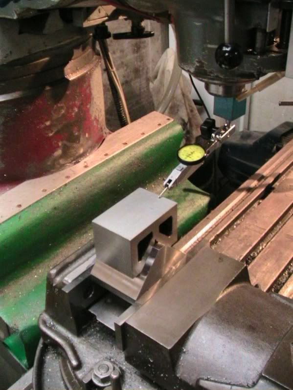
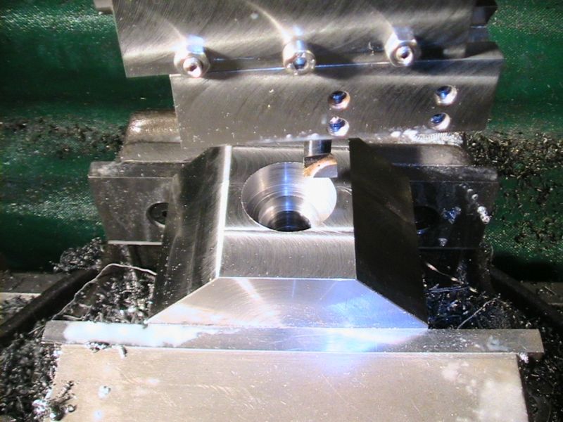
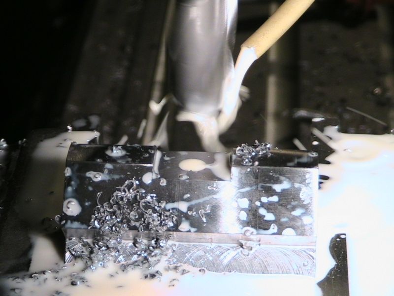
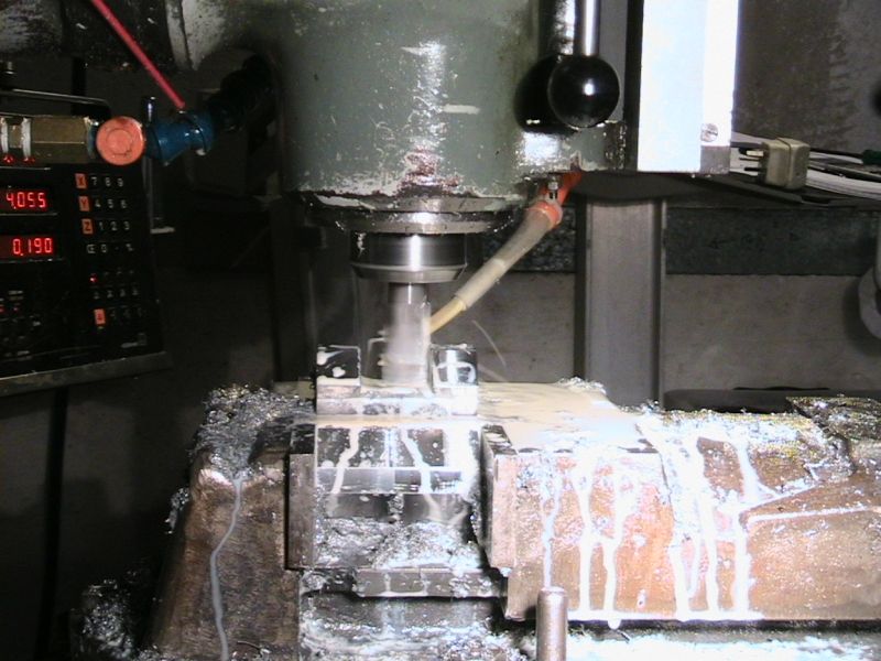
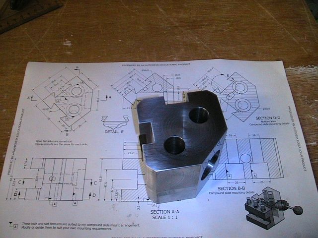
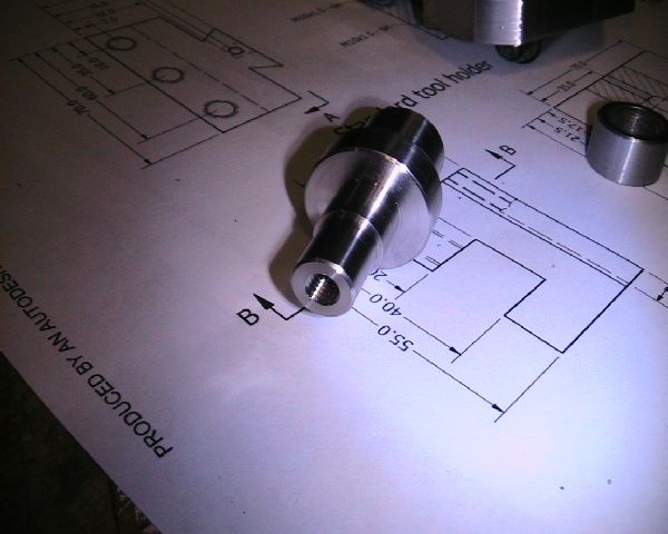
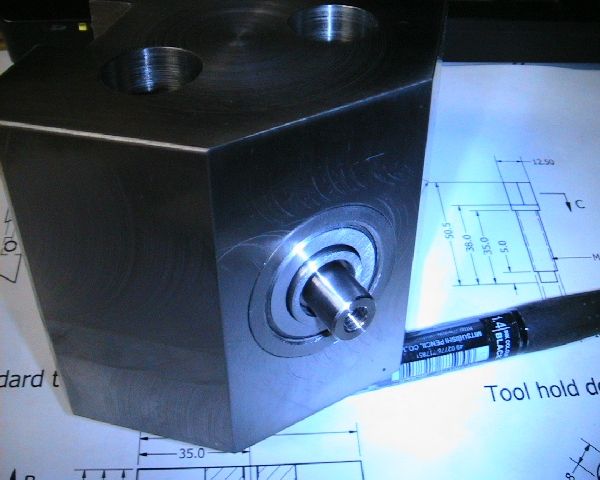
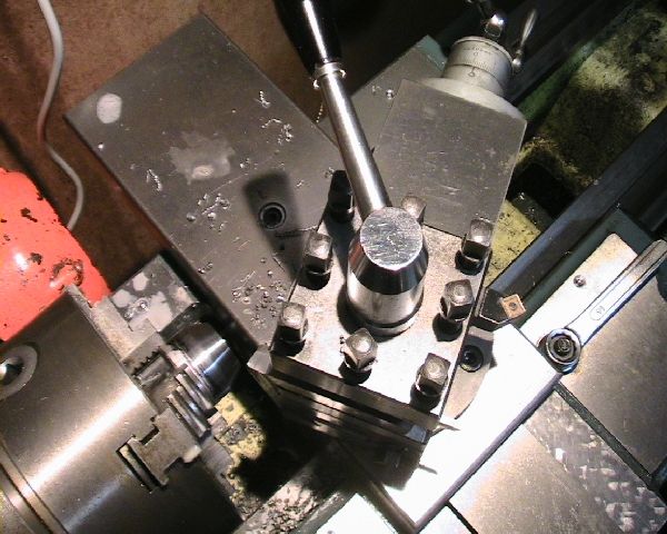
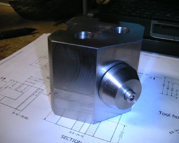
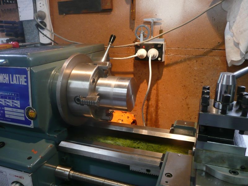
Just thought I might share my progress on making a QCTP for my lathe.
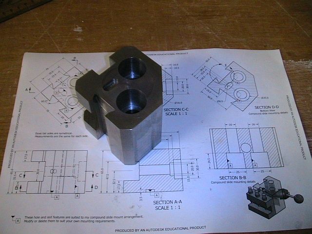
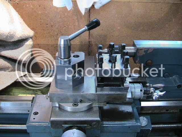
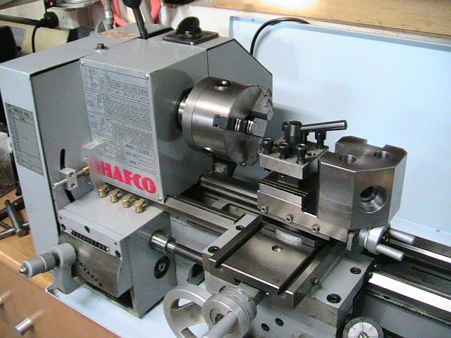
The original tool post is the standard type that is 75mm square and 65mm high. The new tool post is based on a design that pulls the tool holder into the tool post.
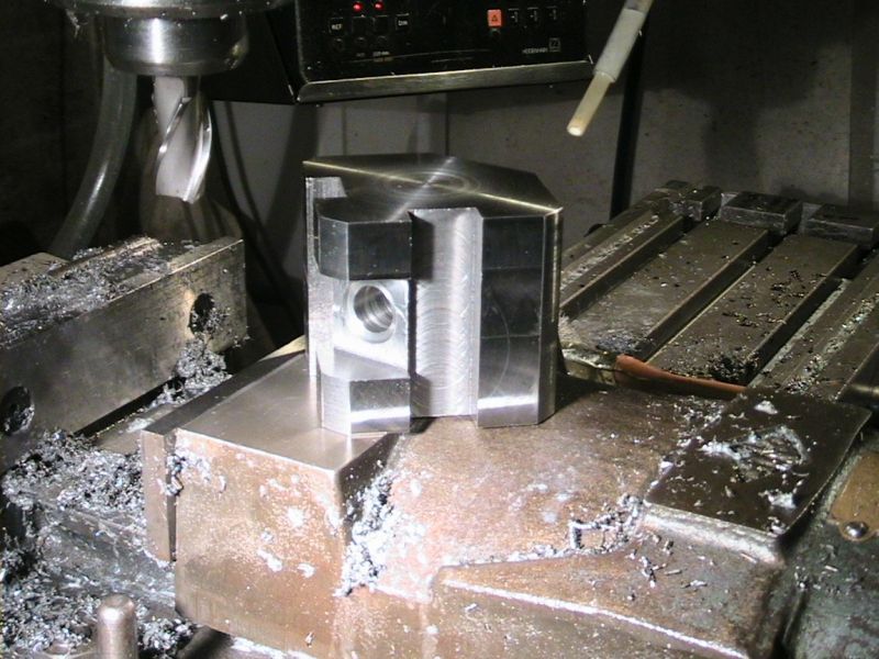
When I finish the QCTP I'll finalize the drawings and post them in the plans section (I imagine I'll have lots of changes due comments and the process of making the parts), but until then here is what I have so far.
Your suggestions and comments are most welcome
Cheers,
Phil
QCTP_70mm.pdf
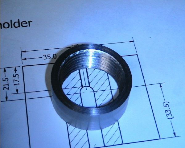
STD_holder_70mm.pdf
These files updated 6-6-09
Changes: dovetail dimensions given using rods 6mm or 1/4" rods
section D-D view direction corrected for looking at base from under side, not from top through.
QCTP_70mm.pdf
STD_holder_70mm.pdf
These files updated 21-6-09
Changes: Drawing now have truncated dovetail corners (chamfered).
View attachment QCTP_70mm_Assembly.pdf
View attachment Parts_70mm.pdf
View attachment QCTP_70mm.pdf
View attachment STD_holder_70mm.pdf
The original tool post is the standard type that is 75mm square and 65mm high. The new tool post is based on a design that pulls the tool holder into the tool post.
When I finish the QCTP I'll finalize the drawings and post them in the plans section (I imagine I'll have lots of changes due comments and the process of making the parts), but until then here is what I have so far.
Your suggestions and comments are most welcome
Cheers,
Phil
QCTP_70mm.pdf
STD_holder_70mm.pdf
These files updated 6-6-09
Changes: dovetail dimensions given using rods 6mm or 1/4" rods
section D-D view direction corrected for looking at base from under side, not from top through.
QCTP_70mm.pdf
STD_holder_70mm.pdf
These files updated 21-6-09
Changes: Drawing now have truncated dovetail corners (chamfered).
View attachment QCTP_70mm_Assembly.pdf
View attachment Parts_70mm.pdf
View attachment QCTP_70mm.pdf
View attachment STD_holder_70mm.pdf

")