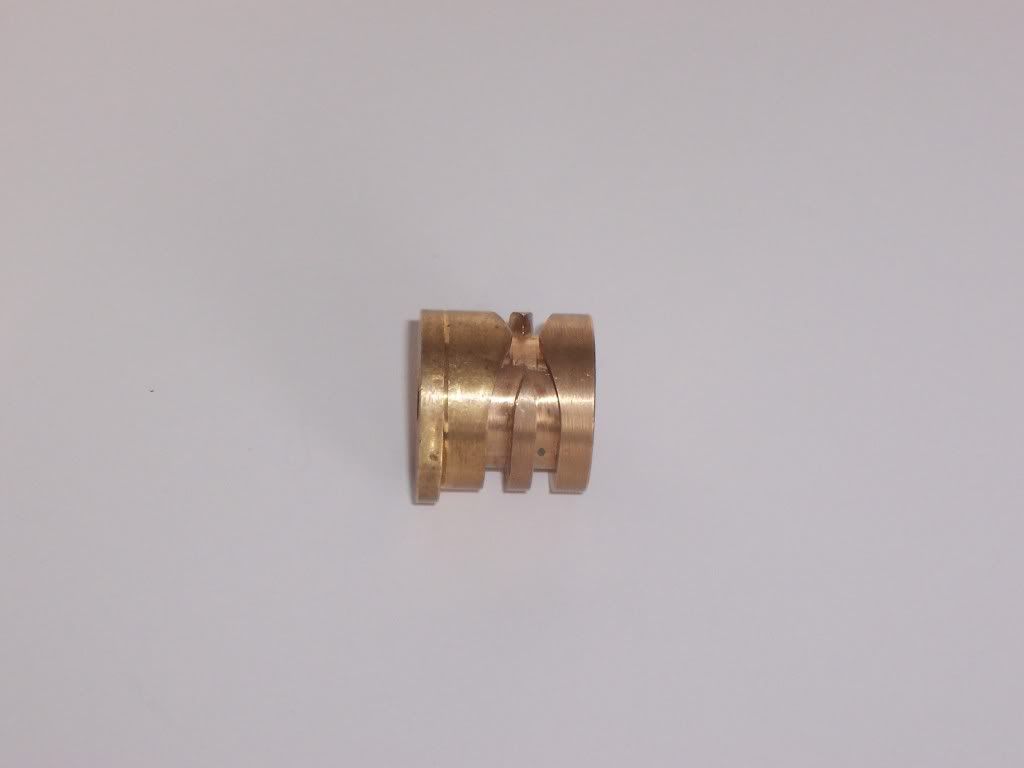
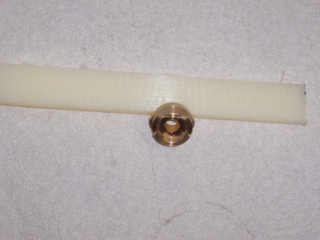
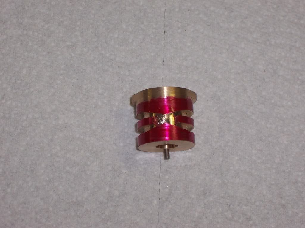
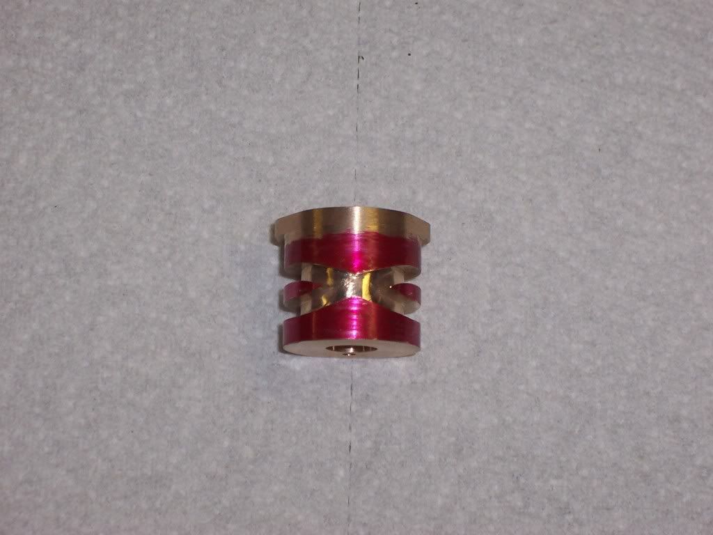
Recently I posted a couple pictures of one of my scratchbuilt engines titled Gearless hit-miss. The engine uses a crossover cam to actuate the exhaust valve. I thought I would post how I made this cam. First I should explain its operation. The crossover cam has a groove cut into the OD that crosses over at one point. It takes 720 degrees of rotation to complete one cycle so the crossover cam is fixed to the crankshaft. I placed a shuttle over the cam that has a stylus attached to it that rides in the groove in the cam. As the cam rotates the stylus follows the groove and positions the shuttle in the proper location. The shuttle has a roller follower in it that rides on the cam. On one revolution the roller follower is off the cam surface and on the next revolution the shuttle positions the roller follower over the cam actuating the exhaust valve. I originally made this cam on a 4 axis CNC machining center but I wanted to be able to do it in the home shop so I had to make it from 3 pieces. The turning of the blanks as I call them is fairly simple so I won't dwell on that process to much. I'll first include a picture of a completed cam for reference.
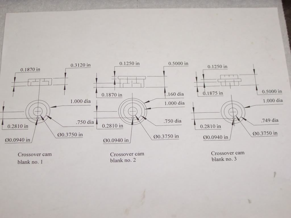
There are 3 blanks that need to be turned to size. The first blank is 1" OD x .312" long with a .375" reamed hole thru it. It also has c-bore of .750" dia x .1875 deep on one side.
The second blank is 1.160" dia x .500 " long. It also has a .375" dia reamed hole thru it and the .750" dia x .1875" deep c-bore, It also has a 1.00"dia x .1875" surface machined on the same end as the c-bore.
The third blank is 1.00" dia x .50 " long. It gets reamed thru .375 also and gets a .749" dia x .1875" dia machined on each end.
Once these three blanks are turned to size I'll move to the mill.
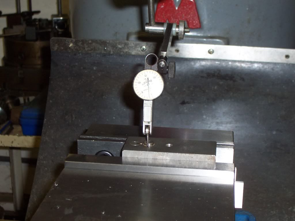
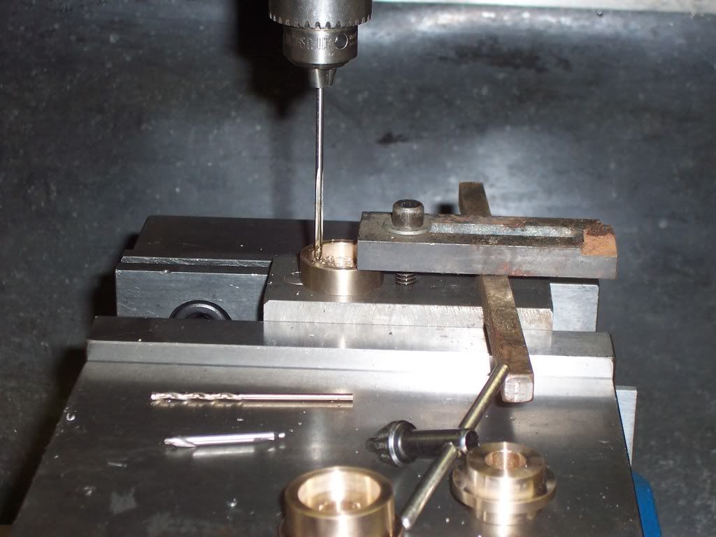
The fixture I used to mill the cam blanks was made from a piece of scrap CRS. It has a .375" dia stud protruding from each side. One side is just a .375 dia pin with .100" stickout above the fixture surface. The other side of the stud is 1.5" long and threaded 3/8-24. The fixture is placed in the mill vise with the short stub side up. Indicate this stub and zero both axis of the mill table. Move .281" on the x axis to locate the fixture so the 3/32 dia holes can be reamed in the blanks. each blank gets a 3/32" dia hole reamed in it .281" from center. This hole positions the blanks on the fixture later and also aligns the blanks at assembly.
The previous picture of the blanks shows these holes already reamed.
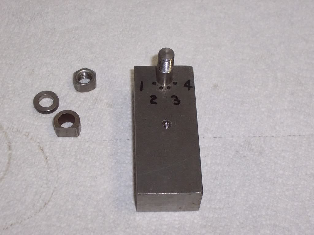
The .375" dia stud is centered in the fixture and located .375" from the top surface of the fixture. The holes marked 1-4 are for locating the blanks with a 3/32" dia pin.
These holes are located from the center of the .375"dia stud. Their locations are:
X Y
#1 -.2433 -.1405
#2 -.0868 -.267
#3 .0868 -.267
#4 .2433 -.1405
These holes are reamed 3/32" x .375" deep. For reference, holes #1&4 are displaced 60 degrees from center and #2&3 are 18 dgrees from center.
The blank that is 1.00" x .312" long is blank #1
The blank that is 1.160" dia x .500" long is blank #2
The blank that is !.00" dia x .500" long is blank #3
Next I'll set the fixture up in the mill and make the cuts for the crossover groove. Dave
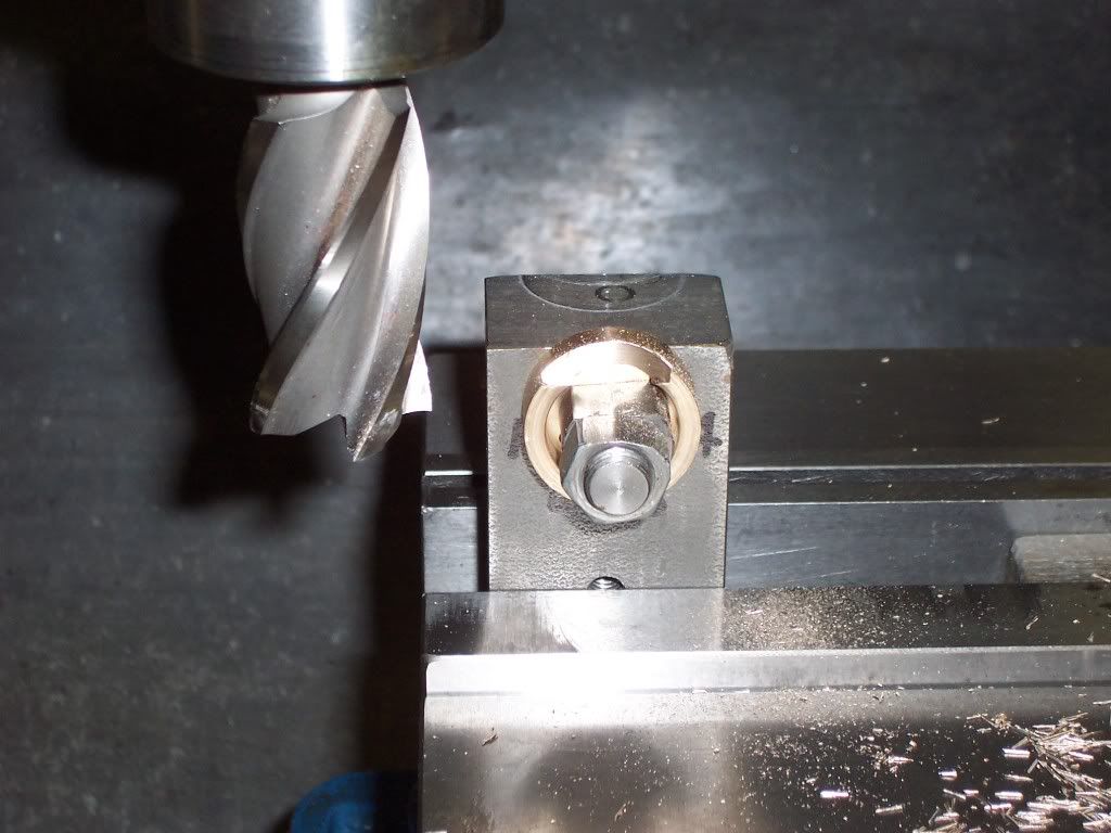
I placed the fixture in the mill vise and indicated the threaded stud to find center. Blank #1 is now placed on the stud and the hole in the blank is aligned with hole #1 in the fixture. The clamp nut is now tightened with a spacer used to give endmill clearance. A 1.00" dia endmill is placed in the mill spindle and then brought down until touching the fixture. The "Z" axis is zeroed and then the endmill is lowered .075". The face of the blank is touched with the endmill to zero the "Y" axis. The endmill is moved off the left side of the blank and then the "Y" axis is moved into the part .125". The endmill cut is only to the center of the blank( "X" 0 ).
This cut will generate the radius for the crossover portion of the cam.
The blank is now unclamped and then rotated until the pin aligns with hole #4 in the fixture. Reclamp and position the endmill at "X" zero( the center of the blank). Advance the endmill into the blank .125" and move the table to allow the endmill to exit to the right of the blank.
Entering the blank from the left of the blank on the first cut above lets you conventional mill the part. To conventional mill the second cut the endmill enters at the center of the blank and then moves to the right.
Now I've generated the 2 radii that will provide tangencies for the groove to crossover. Blank #2 is now given the same cuts as blank #1. Blank #2 is thicker than blank #1 so the "Y" needs to be rezeroed. The depth of cut on blank #2 is also .125".
Blank #2 has the cam portion machined onto it next. With blank #2 still clamped to the fixture and the alignment pin still placed into hole #4 in the fixture, Move the endmill to position it .126" above the fixture top. A cut is taken across the top of the blank to form one cam flank.
Now blank #2 is unclamped and rotated to hole #1 in the fixture again and reclamped. Repeat the last cut at the same depth as before to form the second flank of the cam.
Now that both flank portions of the cam are machined the material between them will need to be removed.
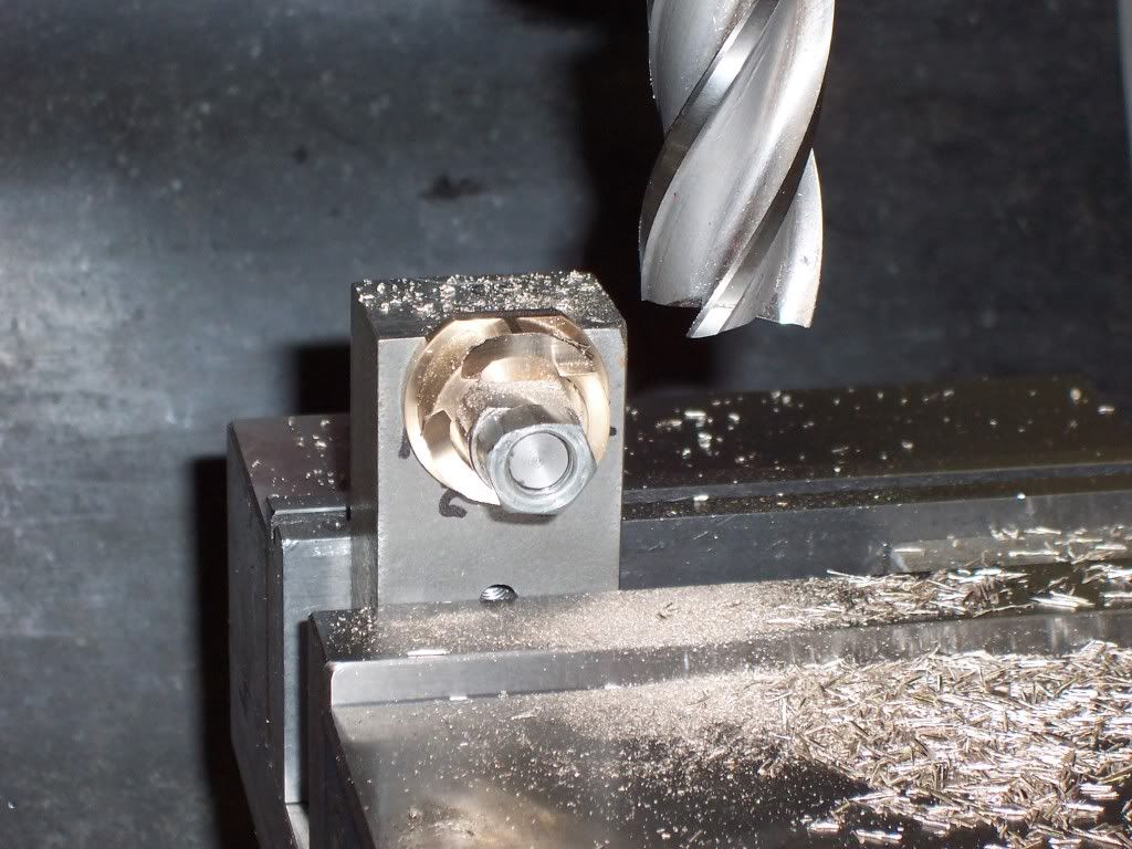
The blank is now unclamped and the alignment pin is removed. The blank is rotated a small amount and another cut is taken. This is repeated until the portion of the cam between the 2 flanks is removed. This will leave 2 cam flanks that are 240 degrees from each other. This cam runs at crankshaft speed so the 240 degrees of cam timing are necessary. The next picture shows the cam with this portion completely removed.
There will be some small facets on this surface that will need to be removed with a file later.
The cam flanks come to a sharp corner and will also need to be radiused later.
A picture of blanks #1 & #2 at this point in the process. The surface for the groove that remains still needs to be machined down .125" to blend with the .500" radii generated in the first cuts. I will need to reposition the fixture to do this but blank #3 needs to be machined first. I will cut this surface later.
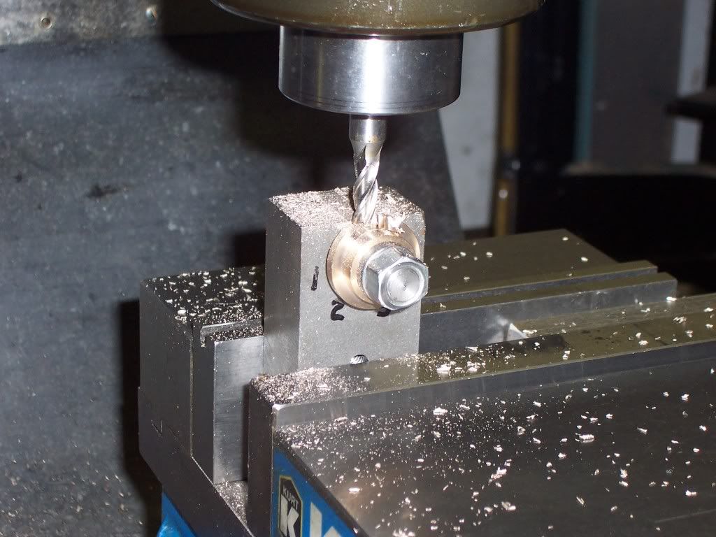
With the spindle still centered with the threaded stud, I placed blank #3 on the fixture with the locating pin aligned with hole #2 in the fixture. A 1/4" dia endmill is now placed in the spindle and the "x" axis is offset to the left .0625". The cutter is brought down to touch the top of the fixture and then raised .002". This cut should leave surface that is .0625 from centerline. Cut through the 1.00" dia portion of blank #3.
Next blank #3 is unclamped and relocated to hole #3 in the fixture and then reclamped. The cutter is offset .0625" in the other direction. Cut through the 1.00" dia. once again.
Once these two cuts are made a small facet will be left in the center of the cuts. I remove the locating pin from the blank and rotate the blank a few degrees and make another cut and repeat until this small peak is removed and then can be cleaned up with a file.
At this point blank #3 gets no more machining done to it. There will be four radii that will need to be filed later.
When making these cuts on the fixture I always turn off the spindle of the mill when repositioning the blanks.
Next I reposition the fixture so the short stub is facing up in the mill vise. Blank #1 is placed on the stub and clamped with a holddown clamp. I use a 1/4" dia endmill to mill the surface between the two radii I cut earlier. This cut is .125" deep.
Blank #2 is machined in the same manner as blank #1.
A picture of the three blanks with the machining done to this point.
Machining is now finished on the blanks. The rest of the work will need to be done by hand with a file. I normally place the fixture in my shop vise with the short stub side up. Blanks #1 and #2 can be filed to shape by being placed on the fixture stub and held with the other hand. I ink up the small raised portion of the blanks and scribe a line in the center to give me a reference point for the filing. I use a fine rattail file to finish the shape and then use a small flat file to point up the center where the two ramps meet. I use a piece of 320 grit paper wrapped around a piece of steel to smooth the ramps.
A picture of the three blanks assembled. Blank #3 ( in the center ) still needs to have the four radii filed on it.
At this point I take a piece of 1/8" square keystock and use it for a scribe to mark how much will need to be filed from blank #3. When properly filed to shape, the keystock should be able to be inserted into the groove and the cam rotated by hand to check for clearance. I made my stylus that fits into the groove in the crossover cam to have about .002" clearance and .625" long with pointed ends.
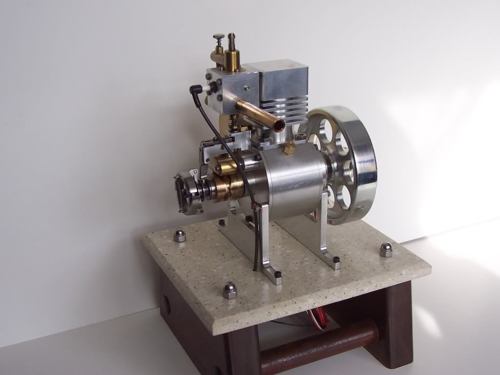
Another picture of my engine I built using this crossover cam device.
Theres a bit of hand work in making one of these cams but it is the best way I have found to make one without a four axis machining center. Give it a try and design your own engine using one of these crossover cams. It's definately not something you see everyday in operation.