Learners Project - Simple Grinding Rest

Home Model Engine Machinist Forum

Help Support Home Model Engine Machinist Forum:

This site may earn a commission from merchant affiliate links, including eBay, Amazon, and others.

joco-nz

Well-Known Member
Joined
Feb 21, 2016
Messages
566
Reaction score
209
Next little project that should result in a nice usable tool and progress general machining experience.

So the game plan is take these blanks
grinding-rest - 1.jpg

and turn them into this simple grinder rest as designed by Harold Hall (http://www.homews.co.uk/page146.html)

LrgGrindRestSim01.jpg


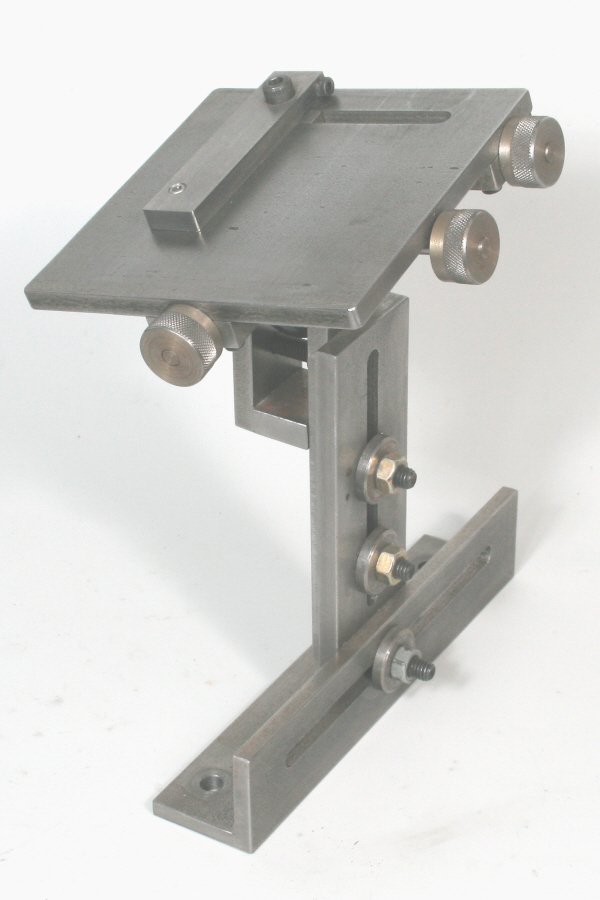
As you can see from the blanks I have lots of cleaning up and shaping to do. The massive angle iron will get cut down to a circa 40x40 size with the cut-offs going into the steel collection bin for use at a later date.
I also have yet to cut off the round bar blanks but will get that done once I get some progress on rectangular parts.

Anyway, hope this little build and the resulting tool will be of interest to some people. The plans are in Harold's book "Tool and Cutter Sharpening" which is #38 of the "Workshop Practices Series" if you are interested in dimensions etc.

Cheers,
James.
 
Ive seen a couple of designs for file rest, this is possibly more complex than I've seen, but will be handy, due to the flexibility, most I've seen fix to the toolpost and consists of two ball bearings, I saw your toolmakers clamp in anther thread, and looking forward to seeing how this project turns out
 
So to help me visualise how all the parts fit together and to allow me to convert some measurements to accomodate some slightly larger stock than the book plans suggest I have been modelling this in Fusion 360. This also forces me to learn Fusion 360 as I see it as a useful tool for later CNC'ing of the Mill. Since it can do both the CAD and the CAM parts of the process. Anyway I digress.

This render gives a good view of how some of the parts below the table will fit together. The various screws etc are missing for clarity.

SimpleGrindingRest_2017-May-08_09-27-13AM-000_CustomizedView25171666410.jpg

Cheers,
J.
 
Right - the start of a mostly sunny looking if cool Sunday down under in NZ. Chips shall be made and the temptation to practice with my TIG welder will be ignored (repeat after me .... "it WILL be ignored").

So today will be trying to get as much metal shaped, drilled and countersunk as my slightly fried brain can achieve. renders of the rests top assembly (still missing a couple of bits) attached. I'm quite looking forward to this tool being usable, its going to make shaping some HSS lathe tools I want to make much easier.

SimpleGrindingRest_2017-May-12_08-54-44AM-000_CustomizedView27233132081.jpg

SimpleGrindingRest_2017-May-12_09-32-56AM-000_CustomizedView31970758487.jpg
 
The results of a whole lot of swarf - Some blanks all nicely machined to size ready to be blued and marked out.

making-chips - 1.jpg
 
Noce little project.

Don't you just love Harold's; site so much information, knowledge and ideas.
 
So the working week has started so just small steps over the next few days. Got a couple of parts done tonight. The two parts that form the vertical adjustment have been milled. There is one lathe operation left to do but until I get the plastic ball delivered then no mad rush to do that.

Pic 1 & 2:
Chain drilling before finishing the slot with a 6mm carbide 4 flute end mill.
making-chips - 1.jpg

making-chips - 2.jpg

Pic 3:
The two parts side by side just to show I'm really making chips and not just doing model renders. :rolleyes:
making-chips - 3.jpg
 
Today was spent largely on another project needed to tidy up the mess of metal in the garage. However after lots of TIG welding and a nearly equal amount of :wall::rant:scratch.gifth_wtf1:redface2: I hung up the TIG torch and played with the mill.

The result being I managed to get a couple more parts progressed. The metal family is growing ...
more-parts - 1.jpg
 
James, I made the advanced grinder rest by Harold Hall. Turned out very well with a few changes. He calls for a slot cut in the shafts so a screw driver can hold the shaft while tightening the lever. I did this at first, then milled the round head to a rectangle .The shaft then fit between the slots in the arms and did not need a screwdriver to keep it from turning. Where Harold clamps a fence at the slots I dispersed with clamps. Instead I milled a small scrap . 249 wide and about .375 deep. I milled a .250 x .125 slot in the accessory plates. The scrap pieces were Loctited in the accessory plates. No need to use a fence as the plate rides parallel to the slots.
The plans are in the Milling book by Harold Hall. So far I have also made the 4 facet drill grinding accessory.
After screwing up a test drill numerous times I finally got it right. I changed the angles some what from the text to get it working for me. I ground about 10 drills from 5/16" to 15/16" with the 4 facet configuration. I tested each one in scrap steel. The 4 facet drills really bored quickly and was easier to start without a spotting drill than the two lip conventional way.
I sharpen a few lathe tools too. I used the front of the wheel for lathe tools and the side for drills. Probably could have used the front or the side for both. I just followed the illustrations and pictures in the book.
Making the parts was pretty straight forward. I work mostly in Imperial and converted the dimensions from metric. I did not have a variety of metric screws , thus converted to Imperial.
Only problem I had was the jibs. Finally tossed the jibs I made from steel and made new ones from brass.
I used 6/32 cap screws for locking that I turned a sharp point on. The screws were turned by running them in a drill against a spinning grinding wheel til the point was sharp. These screws dug into the brass jibs and when I backed them out left an impression. Took a bit of time to get the dovetails to run smoothly and keep the jibs from sliding out.
You can probably grind everything on the original rest that I do on the advanced rest.
mike
 
Wrap-up from as at the end of the weekend ...
I was all gungho to do the dovetails thinking I could use an angle plate set in my vice at the correct milling angle then clamping the parts to this against a fence for reference. The fence idea being that I could get one part all correctly aligned, clamp some steel as a fence on its base so I could mount the other parts for dovetailing in the same spot.

Anyway, it all came apart when I discovered the angle plate will not fit my vice. Its 12mm to big. So looks like I need to get a smaller one or come up with another method for accurately and repeatably mounting this stuff.

However no to be completely daunted I went on to do some other needed operations, some that needed to be done before putting angles on things. So ... drilled and tapped some M5 holes and set up one of the risers that will clamp the 25mm plastic ball on the lathe faceplate (first time ever using this) and got the 30 degree chamber needed to clamp on the ball.

The pics ...

#1: Setting up the part and using a 6mm drill to help align the 6mm hole. It wasn't perfect but for what it will be used for it should be fine. Clamped this as best I could and given its not the most beautiful clamping job set about running at slow speeds (200rpm) and stopping between each cut to check everything was holding.
grinding-rest - 1.jpg

#2: The result. While not the most polished lathe work it should do the job and to be honest a less than mirror finish on this clamping surface is probably a good thing.
grinding-rest - 2.jpg

#3: The M5 holes in all their glory. These were drilled then power tapped on the mill at the slowest speed I have (60rpm). Got to love gun taps.
grinding-rest - 3.jpg

#4: A little bit of a repeat but a nice closeup of the riser arm with the big 30 deg chamber at the top.
grinding-rest - 4.jpg

Cheers,
James.
 
First off was setting up an angle plate with a reference fence to allow for the two outer dovetail blocks to be created exactly the same.

Setting the angle.
cutting-angles - 1a.jpg

A pic to give a clearer view of the little fence I made to allow repeat setting of the blanks for the outside dovetail blocks. I will also use the same setup with no movement for doing the inner dovetail block.
cutting-angles - 1b.jpg

Getting the first part all clamped up and ready for milling. Since the angle plate is a little "in the air" I am taking small nibbles from the top using a 10mm carbide end-mill at 0.3mm per cut to get rid of about 5mm then a final 0.1mm finishing pass to get to size.


Showing the clamp up using my toolmaker clamps. These are starting to prove to be very useful little items. I am going to need to make some more of these.
cutting-angles - 2.jpg
cutting-angles - 3.jpg

The cutting in flight, a nice little pile of swarf appearing.
cutting-angles - 5.jpg

The cut all finished in the clamp setup.
cutting-angles - 6.jpg

The two outer dovetail blocks finished up.
cutting-angles - 7.jpg

The two parts "nose to nose" and looking nice an symmetrical. But just how good was the setup for repeatability?
cutting-angles - 8.jpg

The two parts on a flat surface with 60 degree faces matched up to see how tight a fit they are ... don't know about you but these look pretty dang good for something straight off a mill to me.
cutting-angles - 9.jpg
 
The final part of the dovetails components is the sliding center piece. This part will have the plastic ball attached which will form the main pivot point for the rest.
On the whole the fit between the parts is pretty close and things slide very smoothly. Which is important as the recommendation is to NOT lubricate the dovetails due to all the grinding dust they is going to be about.

Pics attached.
center-dovetail - 1.jpg

center-dovetail - 2.jpg

center-dovetail - 3.jpg
 
Last edited:
A small update since the garage is freezing tonight.

Completed the slot on the table top. Pretty standard process of marking out the ends of the slot, chain drilling the slot then finishing it with a 6mm carbide end mill.

The picture shows the slot and the the dovetail parts placed in position on the underside of the grinding rest top.

table-slot - 1.jpg
 
Some progress today with getting the dovetail blocks mounted on the underside of the rests top. The rest top is 6mm mild steel nominal value, actual size being 5.9mm after cleaning off the mill scale. The M3 threaded holes are drilled 5.3mm deep and then threaded using a bottom tap. The challenge here (per Harold's build instructions) is to get good thread engagement with the bottom tap from the start so as to maximise the amount of usable thread. With the shape of the tap it looks like effective thread depth is about 4.5mm to 4.8mm.

So to solve this problem make a simple tapping jig that contains an M3 tapped hole which the M3 tap goes through. Clamp it to the work and use the fact that the M3 tap will fed down into the hole at the correct rate to ensure a positive threading start from the beginning.

So now for the pics, cose we all want pics right? th_wwp

Pic #1:
Shows the tapping jig and the Irwin tapping attachment I used to get a grip on the tap. Given how thin the M3 tap is this is just turned by hand with no handle and that gives a really good feed for how much tension is on the wee tap.
In the background is the first stage of the process I am describing done with the back M3 screws in place.
table-dovetail-mounting - 1.jpg

Pic #2:
After referencing off the actual hole in the dovetail block the resulting hole drilled to 5.3mm depth and ready for tapping.
table-dovetail-mounting - 2.jpg

Pic #3 & 4:
The tapping jig mounted and ready to start. You can see the nose of one toolmakers clamp used to hold things. Really starting to love these wee clamps. So useful.
table-dovetail-mounting - 3.jpg
table-dovetail-mounting - 4.jpg

Pic #5:
Moving on to the final hole and tapping operation pretty much done. You can see the tapping oil around the hole. The general approach was a drop of oil into the hole before putting the jig in place and some oil on the actual tap itself.
table-dovetail-mounting - 5.jpg

Pic #6:
The final product. Dovetail blocks all mounted up and a nice clean sliding movement from the central block with the M6 screw protruding from it.
table-dovetail-mounting - 6.jpg

Cheers,
James.
 
A little more progress, a lot of learning and fixing some alignment issues on the lathe.

Today was doing the other half of the ball clamping system and after liking the result cleaning up the original clamping part to be a better finish. I also started some of the threaded rods that adjust things. Learning to turn such small diameters (6mm turned down to 5mm) was ultimately successful but the threading using my Frost dies was a failure as the first 5mm just got chewed up until the rubbish dies started to bite properly.

I also discovered quite a bad taper was being turned on the lathe. Some checks showed things were not very flat. Out by between 0.3 to 0.6 degrees in left-to-right and front-to-back respectively. This was resulting in a taper of over 0.1mm across a very short distance. Some adjustments with the digital level and I got the taper down to 0.01mm. The only way I will get things better is to start using some shims between the lathe and the bench top. I'm quite keen to try and get this as good as I can so time to get some aluminium drink cans and start making some shims.

Anyway on to the pics. th_wwp

Pic 1:
Shows the underside with the plastic ball mounted and the (to be replaced) threaded rods in place. If nothing else it has acted as a proof on their function and I know exactly how to go about making them for the next crack.
table-ball-clamps - 1.jpg

Pic 2:
Shows the setup for the final ball clamping part. I figure out a way to get it clamped and not move about plus using the boring bar gave me the reach I needed to avoid bolt heads.
table-ball-clamps - 2.jpg

Pic 3:
The original clamping part in place and cleaned up using this clamping style. You can see a few slimmer clamps that are the beginnings of a low profile clamping set. There is also a lone mill-clamp on the edge which was needed to balance out the weight on the face plate.
table-ball-clamps - 3.jpg

Pic 4:
The two clamping parts and the dovetail with plastic ball mounted.
table-ball-clamps - 4.jpg

Pic 5:
Simple "dry" assembly to show how things will get clamped. Still need to make the spacer that will go at the base of the shorter clamp.
table-ball-clamps - 5.jpg

Cheers,
J.
 
was ultimately successful but the threading using my Frost dies was a failure as the first 5mm just got chewed up until the rubbish dies started to bite properly.

I have similar issues and find that cutting a gentle chamfer on the end of the rod to be threaded helps a lot. The die is allowed to gently and progressively engage and by the time maximum cutting force is needed there is enough engagement of the die to allow it to continue cutting. Once it's done I then clean up the tapered end. Some parts don't allow this method but for making bolts and the like it works just fine.

The other thing I do is turn the major diameter of the blank a little smaller than nominal. Say a 5mm 'bolt' I would turn the blank to 4.92ish, then run the die over it. Seems to make life a bit easier for the die and the results are acceptable (to me at least).
 
Thanks Cogsy. I did put a pretty hefty 45 degree chamfer on things but not a taper. I'm going to borrow a mates good HSS M5 die and try that while I wait for my own button die order to arrive. But the sacrificial taper could be a viable option on these parts.

Cheers,
James.
 

Latest posts

Back
Top