Kozo's wiggler/center test indicator

Home Model Engine Machinist Forum

Help Support Home Model Engine Machinist Forum:

This site may earn a commission from merchant affiliate links, including eBay, Amazon, and others.

ChooChooMike

Well-Known Member
Joined
Jan 5, 2008
Messages
864
Reaction score
13
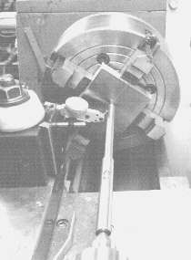
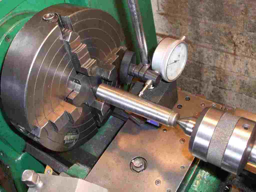
Has anyone made Kozo's wiggler/center test indicator from his Building the Shay book ?

If so, I'm curious as to what dimensions you used. His are in metric, so wanted to see what was used in place of those.

e.g. the rod diameter is 2mm = 0.0787. Guess you could substitute 1/16" or 3/32" for that or Enco has 2mm drill rod. Hmmm.

I realize the dimension aren't really that critical for what it does.

Here's 2 pages with few pictures :

http://www.thms.tedatum.com/PenA3/HTML/PA3_journals.html

DSC03390.jpg


http://www.thms.tedatum.com/shop16.html

DSC03361.JPG

 
When starting out, I made several variants of that. (Remind me and I'll bring them to our next meeting if you wish.)

They're all too fiddly to use for my tastes. Make yourself a pump center and be done with it. Quicker setup and you get a numerical reading on the DI instead of trying to suss out where that pointer is pointing "on average".
 
Marv,

Make yourself a pump center and be done with it.

What is a pump center ? Is that a widget to attach a DI somewhere like a tool post ?

Mike
 
Everyone I see using those wigglers makes it tough on themselves.
If you turn it around so the short end is facing the Tailstock it settles down much faster!! ;)
 
The one I made, I greatly simplified the construction of it by using a piece of rubber from a dog chew toy to hold the shaft inside the tool stem. Don't need to be finding brass balls.
 
You can make them real simple. Even just a rod with a 60 degree point at one end and center drilled on the other.

Here is one in use to dial in a feature on that part:

4JawDialIn.jpg


Nicer ones are out there too if you want to spend the time spring loading and whatnot.

Many variations on this technique on my eccentric turning page:

http://www.cnccookbook.com/CCLatheEccentricTurning.htm

Best,

BW
 
ChooChooMike said:
Here's the pix from that page :

pmpcdwg.gif
[/center]

Hmmm, looks simpler ?
I made one of those a while back. It doesn't get used much because I don't do much 4-jaw work.

When it does get used, it works pretty well, though I'd be tempted to use larger diameter parts were I to do it again.. 3/8 is a tad annoying to get the indicator square onto (yes, you probably don't have to.. ). The slot and pin are to keep the spring-loaded parts from springing apart in storage and making themselves difficult to find. I skipped them since I had got lucky and got a great fit on the tailpiece that keeps it in place without.

I think the best advice for 4-jaw work is Marv's suggestion to make another chuck wrench so you can adjust both opposite jaws at the same time. That is the way to go.

 
heres a classic

i'm sitting here watching this and thinking pump centre??? What the...

In Oz ( or I do any way) we call them a "sprung centre or sprung pin"

i know the kiwis do too ( New Zealanders) maybe the brits do too , but dunno

real handy bit of kit. especally with stainless and ALU or slippery stuff

i like marker pens i put some in in the middle where my measure is

mark it across the ink chuck it up and bring the tailstock and centre up and lock off

wind the TS and centre forward to put the point on the centre marks and add just enough pressure so it holds

bring in your DI and adjust to the shaft, then rotate the chuck by hand ( I turn about 1/6 th i think the book says 1/4 turns though ) and watch the DI as a quicky indication and adjust as required

a deft pressure adustment will, once your happy centre is centre,
put enough of a mark on the surface to centre a drill or what you wish.

cheers

jack
 
3/8 is a tad annoying to get the indicator square onto (yes, you probably don't have to.. )

Make a flat, plate-like "point" for your DI. Picture a 1/16" thick disk 1/2" in diameter with a tenon threaded 4-48 to attach to your DI. Then you don't need to worry about getting things on center.

[For centering work, I don't use a DTI set up on a magnetic base holder as is shown in some of the pictures in this thread. I use a dedicated DI on an adjustable mount.

BOUNCER.jpg


It has an attached magnet so it can be slapped in place on the compound and will be automatically aligned with the spindle axis. The picture shows the rig with a "flapper" attached for centering square stock in the 4jaw but normally the flapper is removed.

I do a lot of 4jaw work and this arrangement is faster and more convenient than faffing about with an adjustable indicator holder.]

 
mklotz said:
It has an attached magnet so it can be slapped in place on the compound and will be automatically aligned with the spindle axis.
Can you elaborate on the magnet and automatic alignment part (perhaps elsewhere to avoid drifting the thread too much)? I'm not picturing it, but it seems really handy. Besides, I like magnets ;)
 
wow im learning more and more here. i really like marvs idea too that is a dandy device.
i love this place & you guys are a wonderful bunch.
i thank you all for sharing your great ideas with all of us newbies
 
shred said:
Can you elaborate on the magnet and automatic alignment part (perhaps elsewhere to avoid drifting the thread too much)? I'm not picturing it, but it seems really handy. Besides, I like magnets ;)

The magnet (hidden on the bottom of the angle plate to which the DI is attached) simply secures the device to the top of the compound - nothing special about it except it's big and strong so the DI holder can't move around.

In my picture you can see the (black) forked piece that allows the DI to be moved vertically so that the DI axis can be aligned to the lathe spindle axis.

When I build tools like these I work on the principle that, being the lazy sod I am, the tool should be very quick to set up for use. This helps ensure that I'll use the proper tool rather than some half-a$$ed jury rig just to save a couple of minutes. So far this adjustment based on my self-pschoanalysis has worked well. I seldom jury rig and do better work because of it. I find it very worthwhile to build such dedicated jigs.

This thing literally drops in place and is ready to go. Normally, the DI has the disk-shaped tip I described in place but, for some reason when this photo was taken, I had a conventional tip fitted.

BTW, a more complete discussion of the "flapper" you see attached in the picture is given in one of my previous threads:

http://www.homemodelenginemachinist.com/index.php?topic=627.0
 
mklotz said:
The magnet (hidden on the bottom of the angle plate to which the DI is attached) simply secures the device to the top of the compound - nothing special about it except it's big and strong so the DI holder can't move around.

In my picture you can see the (black) forked piece that allows the DI to be moved vertically so that the DI axis can be aligned to the lathe spindle axis.
Ah, I think I get it. I was thinking you had some clever way to set the DI orthogonal to the spindle axis, especially as my compound is usually at some odd angle, but as long as it's on center, it'll be usable for 4-jaw centering purposes.

I'm with you on the lazy-tool-setup mentality.
 
Tin, that looks like the one I built years ago. I don't use it very often, but it doesn't take up much room in the tool box and is there when I do need it. These little gadgets are invaluable when you need them.
 
Back
Top