


Sshire
Well-Known Member
- Joined
- Jun 29, 2011
- Messages
- 936
- Reaction score
- 259
Bill Reichart's Gyro Engine is the 2nd of his that I have completed. The Epicyclic was a long build but the plans are first-rate, the fixtures in the plans are a help and I was intrigued by the rotating cylinder so I ordered the plans and began.
The first thing I noticed was how few parts there are. The major sections are:
1. Flywheel
2. Cylinder, piston and rod
3. Valve
4. Two supports.
A few other bits and that's pretty much it.
As I said, I like Bill's drawings and fixtures but, some of his design elements (like flywheel spokes) are a bit "Victorian" for me so I did change those and the supports.
After building six other engines this year, it seems that the air intake locations feel like an afterthought by the designer with air hose just waiting to wrap around the flywheel. ("Elmer, it's time for dinner" "OK, let me just stick this air intake somewhere and I'll be right there")
I redesigned the front support so that the intake could come through the base with the hose exiting at the bottom rear.
Flywheel
I started with a piece of 6061 0.5" aluminum plate and drilled a hole somewhere near the center with a 2.75" hole saw (the largest I had)
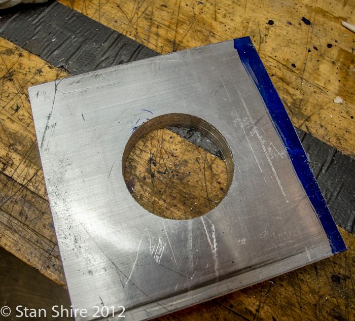
Next step was to rough out (very rough) something approaching a circle on the bandsaw.
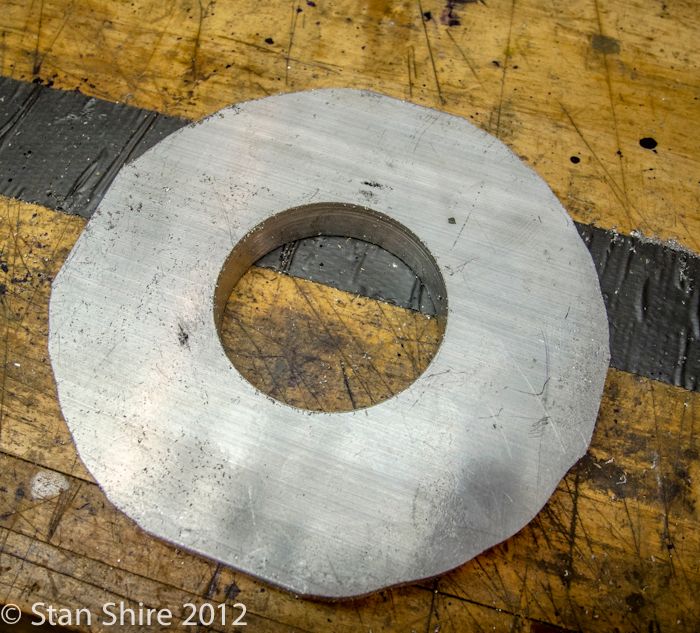
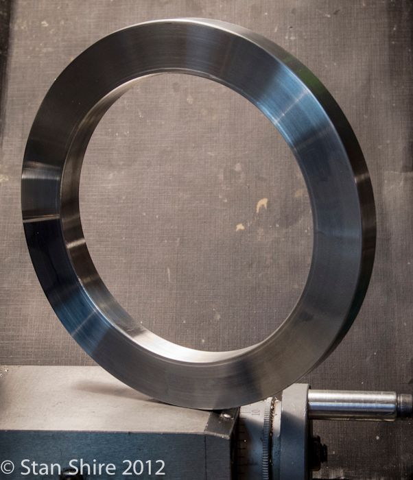
Mounted it on the three-jaw and faced the front and back and turned the outer rim to size. I'm using Arthur Warner HSS indexable tooling throughout.
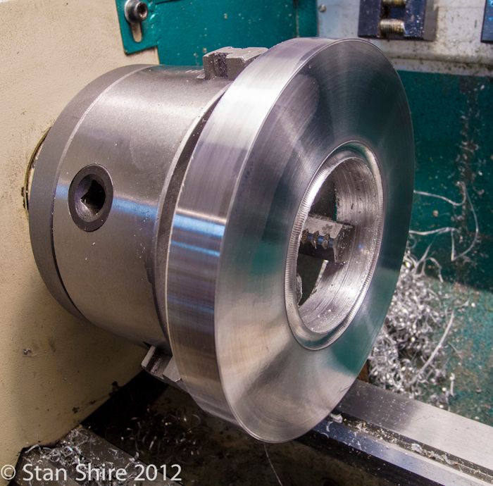
I switched to the four-jaw chuck to grip the outer rim and bored the inner rim.
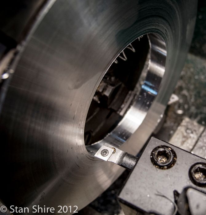
Rim done
I decided to use brass hex for the flywheel spokes. I machined them to length with Bog's idea for the stop. 3MT stub mandrel in the spindle bore behind the Bison 5C chuck. Threaded rod through the mandrel, etc. Search around MEM for his post. I had used a 5C stop in the past and things were pretty close in length. These 6 spokes were all less than a half-thou. Amazing!
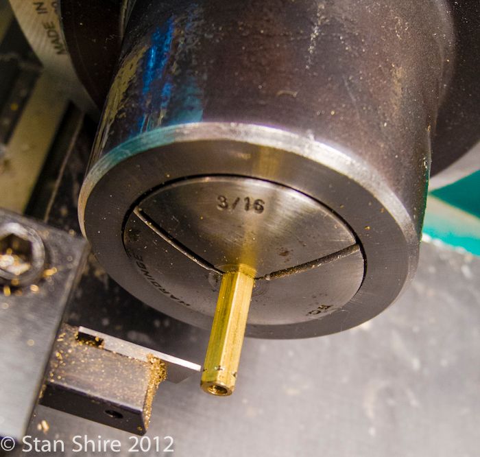
Drilled and tapped them while they were still on the lathe. The hub is 6016 hex with a brass press-fit insert bearing.
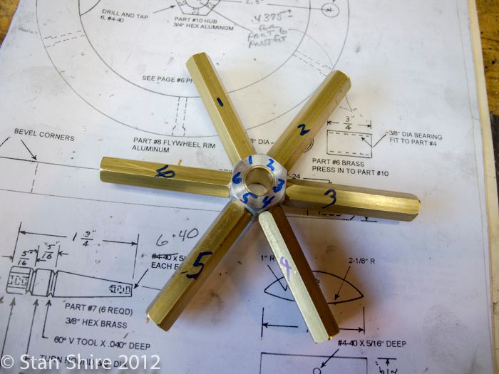
The reason for numbering was when I had done this in the past, there was a round of filing each one to length so this was a habit. Turns out the length was so exact that there was no filing and the position makes no difference.
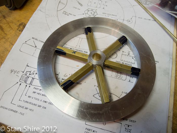
Flywheel done.
Cylinder and Heads
Get a Keats Angle Plate. (Again, thanks to Bogs for that gem). Forget the shipping of cast iron from the UK. This was worth it.
I milled the cylinder block about 50% longer than the drawings. This was so that when I cut it to length before putting it on the lathe, I'd have another piece that was exactly the same dimensions to turn the top and bottom heads.
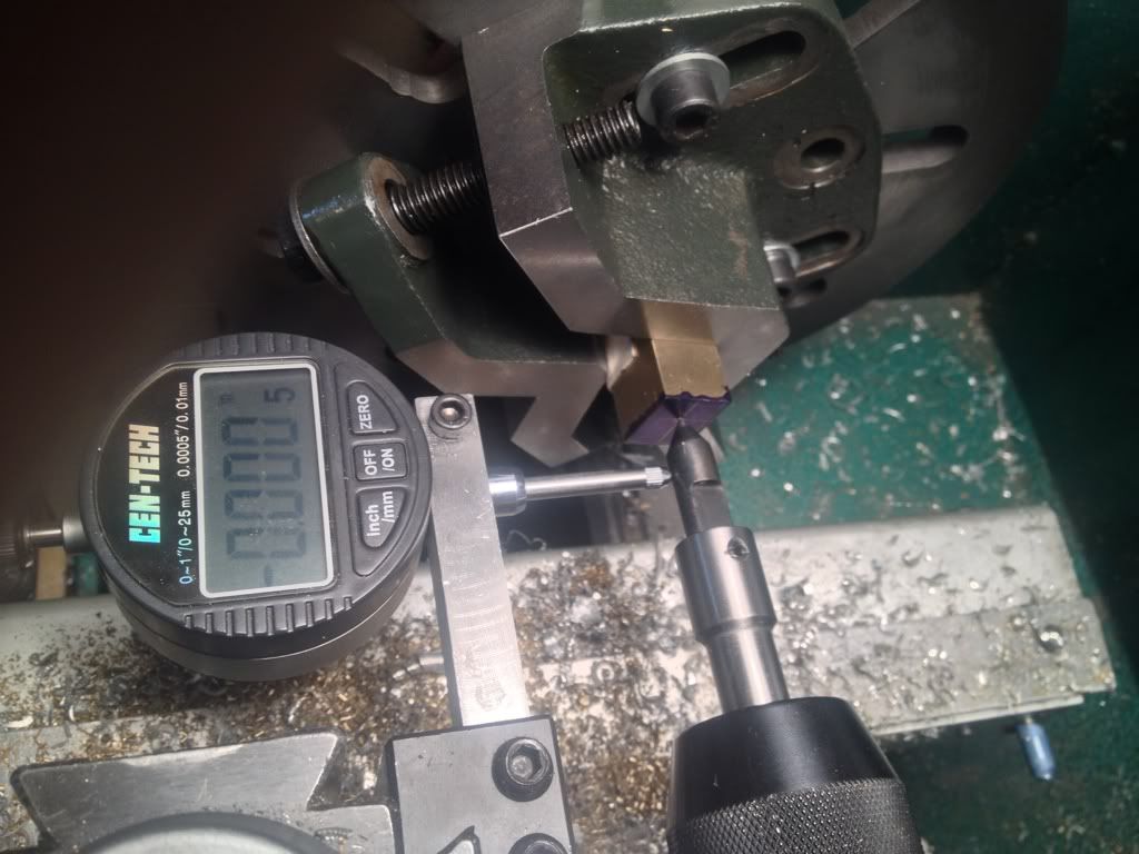
I marked up the milled block to punch the offset location for the cylinder bore and then mounted it in the Keats plate.
After I took this picture i was able to tap the Keats into position so that the indicator was dead on zero.
Drilled and reamed to size.
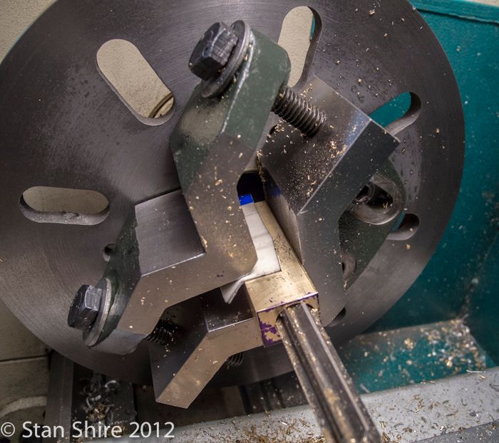
The neat thing I realized about the Keats vs the 4 Jaw is that I can use any thickness cardboard, soda can, etc. to protect the part and change it since it's registered on the bottom V.
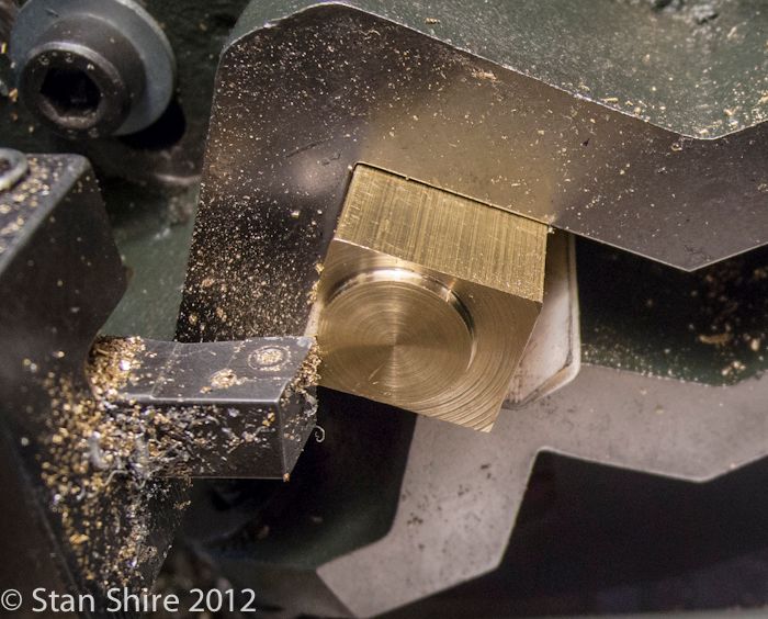
Now comes the real test. I replaced the cylinder with the other piece of brass (remember this was originally from the same milled piece as the cylinder), tightened up the bolts and turned and parted off the top and bottom heads.
The test fit was perfect. Everything lined up. A miracle based on past performance.
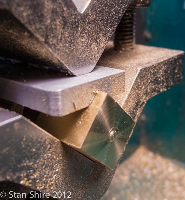
I did later make a "V-block" to replace the soda cans and cardboard.
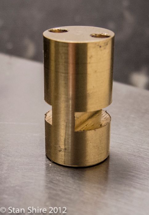
Next, a recess was milled in the side of the cylinder for the valve. Drilling of air passages later ensued.
Intermission
Not sure how this ended up in my build pix folder but I thought I'd include it here. Are there any other countries left?
The Valve
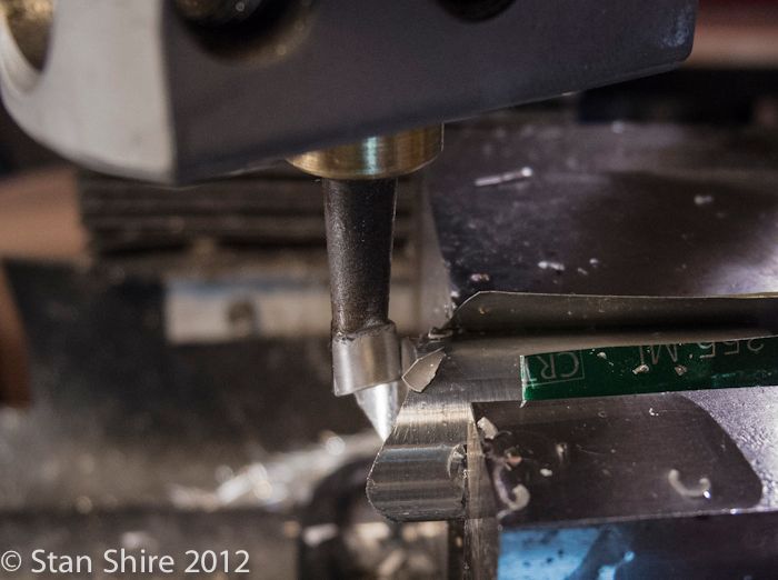
Fairly straightforward milling and drilling. Turned to diameter and it stayed in the collet for the drilling and milling.
The air passages are drilled.
Flats milled
And done
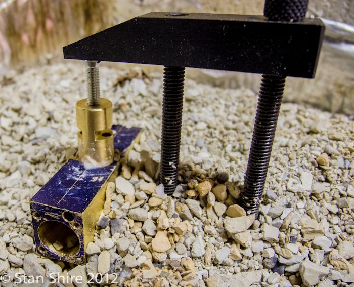
Next, the valve is silver soldered into the cylinder. The plans suggested drilling and tapping a blind hole at the end of the valve. A flathead screw is put in and provides bearing for a clamp.
You can see the air passage and the 4 2-56 holes at the end of the cylinder.
Also, I've found that Kitty Litter (under the part) is an excellent insulator and the parts seem to heat faster and more evenly. Also good if you have a cat.
Supports
I mentioned that I wasn't totally excited about the look of the supports. Too square and inelegant.
After sketching a few designs I decided to make everything round.
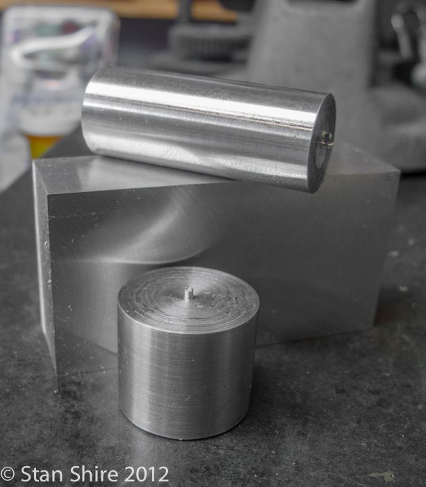
I began with these pieces.
To fit the top, I used the boring head on the mill and did an interrupted cut
Kept checking until it fit perfectly
Now I had this
Marked out an arc on the bottom part
Then onto the rotary table to round it off
and put together
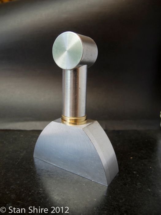
The front support, which has the brass air inlet pipe running up through it, used the same procedure for the post and top. The bottom
was to be an open half-circle.
Mounted a drilled block on a 5C expanding collet.
Turned it round and put a 45 degree bevel on.
When I have a part that has more than one operation, I generally make a list of operations in order.
Like this.
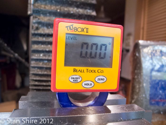
After cutting the ring in half, I got it leveled on the mill.
I have had too many of these electronic levels go bad. They all seemed to be made in the same factory.
This one, however, is built like a tank. Works flawlessly, and if it doesn't, I can call J.R. Beall (himself) who will make it right. Even after hours, he'll frequently answer the office phone from home. No relationship with them; just love companies like that. They make mostly woodworker related tools, but occasionally, one is multi purpose.
So, face mill mounted and bottom flattened.
And the top
So it looks like this
And with everything polished and bolted onto the base

Thanks for looking
Stan
The first thing I noticed was how few parts there are. The major sections are:
1. Flywheel
2. Cylinder, piston and rod
3. Valve
4. Two supports.
A few other bits and that's pretty much it.
As I said, I like Bill's drawings and fixtures but, some of his design elements (like flywheel spokes) are a bit "Victorian" for me so I did change those and the supports.
After building six other engines this year, it seems that the air intake locations feel like an afterthought by the designer with air hose just waiting to wrap around the flywheel. ("Elmer, it's time for dinner" "OK, let me just stick this air intake somewhere and I'll be right there")
I redesigned the front support so that the intake could come through the base with the hose exiting at the bottom rear.
Flywheel
I started with a piece of 6061 0.5" aluminum plate and drilled a hole somewhere near the center with a 2.75" hole saw (the largest I had)
Next step was to rough out (very rough) something approaching a circle on the bandsaw.
Mounted it on the three-jaw and faced the front and back and turned the outer rim to size. I'm using Arthur Warner HSS indexable tooling throughout.
I switched to the four-jaw chuck to grip the outer rim and bored the inner rim.
Rim done
I decided to use brass hex for the flywheel spokes. I machined them to length with Bog's idea for the stop. 3MT stub mandrel in the spindle bore behind the Bison 5C chuck. Threaded rod through the mandrel, etc. Search around MEM for his post. I had used a 5C stop in the past and things were pretty close in length. These 6 spokes were all less than a half-thou. Amazing!
Drilled and tapped them while they were still on the lathe. The hub is 6016 hex with a brass press-fit insert bearing.
The reason for numbering was when I had done this in the past, there was a round of filing each one to length so this was a habit. Turns out the length was so exact that there was no filing and the position makes no difference.
Flywheel done.
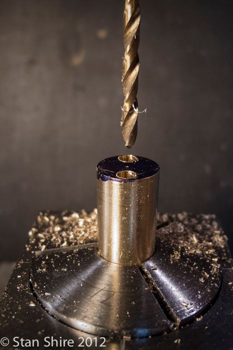
Cylinder and Heads
Get a Keats Angle Plate. (Again, thanks to Bogs for that gem). Forget the shipping of cast iron from the UK. This was worth it.
I milled the cylinder block about 50% longer than the drawings. This was so that when I cut it to length before putting it on the lathe, I'd have another piece that was exactly the same dimensions to turn the top and bottom heads.
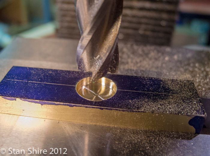
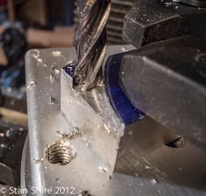
I marked up the milled block to punch the offset location for the cylinder bore and then mounted it in the Keats plate.
After I took this picture i was able to tap the Keats into position so that the indicator was dead on zero.
Drilled and reamed to size.
The neat thing I realized about the Keats vs the 4 Jaw is that I can use any thickness cardboard, soda can, etc. to protect the part and change it since it's registered on the bottom V.
Now comes the real test. I replaced the cylinder with the other piece of brass (remember this was originally from the same milled piece as the cylinder), tightened up the bolts and turned and parted off the top and bottom heads.
The test fit was perfect. Everything lined up. A miracle based on past performance.
I did later make a "V-block" to replace the soda cans and cardboard.
Next, a recess was milled in the side of the cylinder for the valve. Drilling of air passages later ensued.
Intermission
Not sure how this ended up in my build pix folder but I thought I'd include it here. Are there any other countries left?
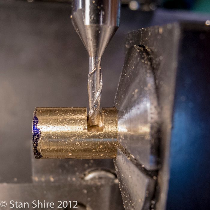
The Valve
Fairly straightforward milling and drilling. Turned to diameter and it stayed in the collet for the drilling and milling.
The air passages are drilled.
Flats milled
And done
Next, the valve is silver soldered into the cylinder. The plans suggested drilling and tapping a blind hole at the end of the valve. A flathead screw is put in and provides bearing for a clamp.
You can see the air passage and the 4 2-56 holes at the end of the cylinder.
Also, I've found that Kitty Litter (under the part) is an excellent insulator and the parts seem to heat faster and more evenly. Also good if you have a cat.
Supports
I mentioned that I wasn't totally excited about the look of the supports. Too square and inelegant.
After sketching a few designs I decided to make everything round.
I began with these pieces.
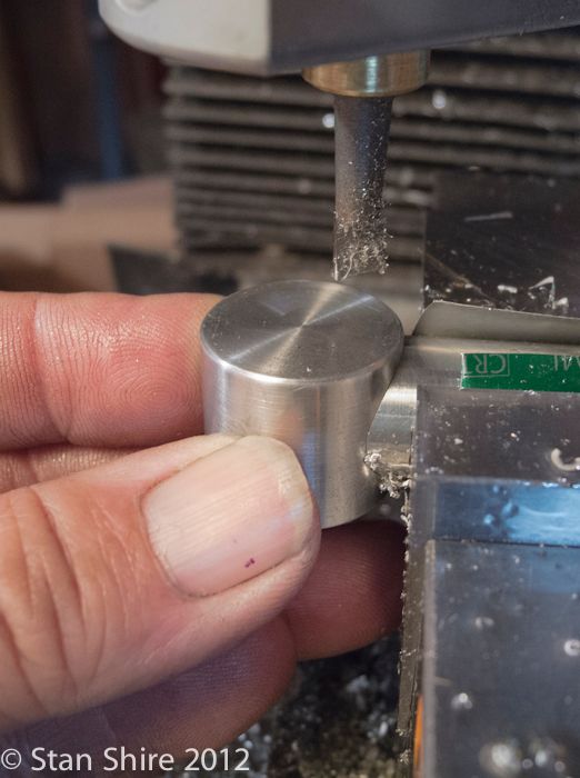
To fit the top, I used the boring head on the mill and did an interrupted cut
Kept checking until it fit perfectly
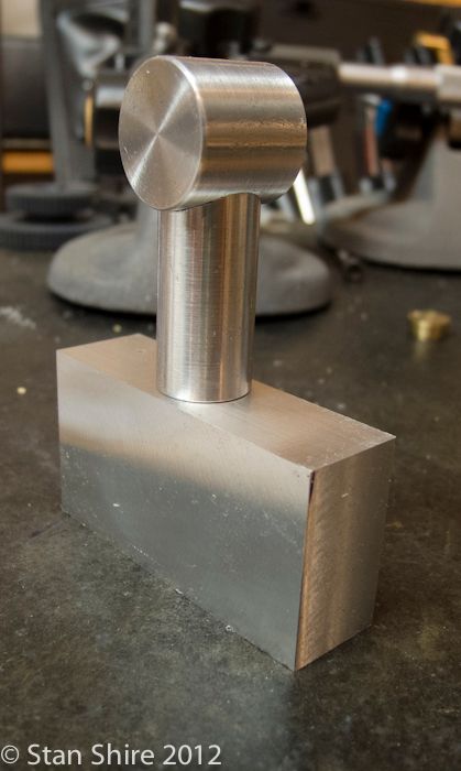
Now I had this
Marked out an arc on the bottom part
Then onto the rotary table to round it off
and put together
The front support, which has the brass air inlet pipe running up through it, used the same procedure for the post and top. The bottom
was to be an open half-circle.
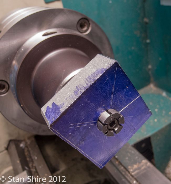
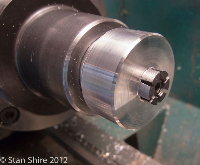
Mounted a drilled block on a 5C expanding collet.
Turned it round and put a 45 degree bevel on.
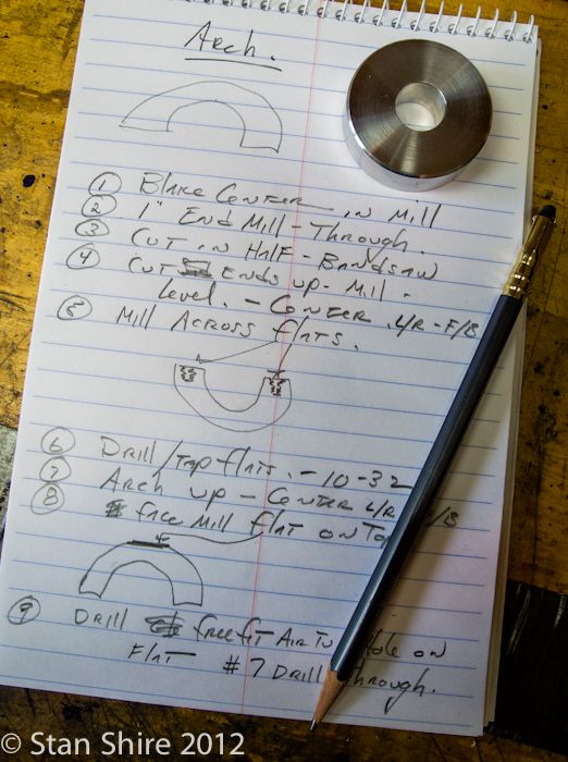
When I have a part that has more than one operation, I generally make a list of operations in order.
Like this.
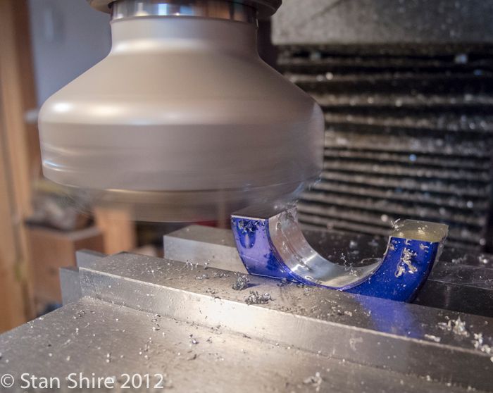
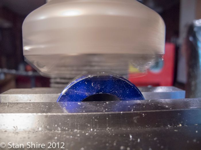
After cutting the ring in half, I got it leveled on the mill.
I have had too many of these electronic levels go bad. They all seemed to be made in the same factory.
This one, however, is built like a tank. Works flawlessly, and if it doesn't, I can call J.R. Beall (himself) who will make it right. Even after hours, he'll frequently answer the office phone from home. No relationship with them; just love companies like that. They make mostly woodworker related tools, but occasionally, one is multi purpose.
So, face mill mounted and bottom flattened.
And the top
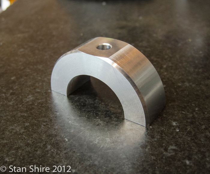
So it looks like this
And with everything polished and bolted onto the base
Thanks for looking
Stan
") Video sometime soon ?
Video sometime soon ?