Horizontal Mill Engine From Kit

Home Model Engine Machinist Forum

Help Support Home Model Engine Machinist Forum:

This site may earn a commission from merchant affiliate links, including eBay, Amazon, and others.
Marv: I remember the discussion on the zombie center. One more of these crankshafts (and there will be) and I'll for it.

Yeah I'd rather fix the crankshaft too. But wondered about bearing.

Robert: Thanks. That's how I saw the runout. I was measuring every once in a while but didn't think there was anything I could do about it once I was cutting. When I get a chance...it's another area of experimentation.
 
Looking Good Zee Thm: i see your getting allot of practice turning thin parts and up to a shoulder ;)
Regards Rob
 
RobWilson said:
i see your getting allot of practice turning thin parts and up to a shoulder

Yep. I'm getting real good at making bad parts. :big:

Thanks Rob.

 
Hows It go Zee , THE MAN WHO NEVER MADE A MISTAKE ,NEVER MADE ANYTHING. think that's it :big:
Regards Rob
 
Yep, if you ain't breakin' parts, you ain't makin' parts... or something like that.

there's a fine line between Zero and Hero. With CNC, you can kill parts even faster...and all alike.
 
Rob and Vernon...

Yeah...I have no problem taking my worst part into work, showing it off, and betting anyone they can't make one like it. Ha! They don't even try. :big:
 
Off topic...

I trammed my mill today and am pretty happy with the results. So I wanted to have some fun (I mean some additional fun).

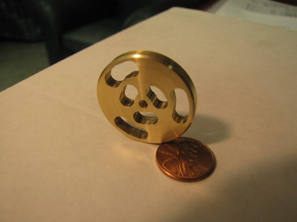
Made this...

IMG_0459.jpg


Overall...it was a great experience.
Faced and turned to size on the lathe.
Drilled and reamed the hole.
Mounted the rotary table on the mill.
I couldn't believe how much easier it was to square and center the table to the mill. (Now that I knew the DTI was in tenths of thou...and the practice from last time.)
Moved the chuck to the rotary table.

What I was trying to do was make slotted holes. They are in the pattern used for a quadrature encoder. (A couple of LEDs and phototransistors and you can measure distance and speed in either direction. From my old robot days. Not that I'm going to do that...just wanted this flywheel to be a little different. ;D)

First slot was pretty bad. Plunged then turned the table. After that I plunged the ends and the middle and then turned the table to clean up.

Then back to the lathe...faced again to clean up the edges.
Then parted. Stalled once but kept my pants dry.

Not exactly what I'd hoped...but it was good learning. I'll probably try my hand at filing and sanding and see if I can improve the appearance.

Then I'll need to find a use for it. Have no idea at the moment. ::)
 
Ok, that one got an "Oh, NICE!!!" from me, out loud. Kid agrees.

Figures your first RT part would be an encoder wheel. ;D
 
First slot was pretty bad. Plunged then turned the table. After that I plunged the ends and the middle and then turned the table to clean up.

Yes! Good onya! You're learning to detect what you're doing wrong and, more important, developing a sense of how you have to modify your approach to correct it. They call that... wait for it ... experience.

When you do larger flywheels, you won't be able to cut the contour in one pass (if you do, the walls of the slot will be rough) so you'll need the drilled holes at the end of the slot to provide a place to put on the next cut increment if your endmill isn't center cutting. Those end holes are also great for reminding you when to stop turning the RT. It's really easy to zone out on a tedious job like that go too far. DAMHIKT.

Then I'll need to find a use for it. Have no idea at the moment.

Come on, you can't fool us. You want to build a rocking engine. That flywheel looks just about the right size.

Think of the trash talking you can do at work. "Yeah, guys, I was having a problem with the mill engine I'm building so, while I was working out how to solve it, I built this rocking engine."
 
Flywheel's looking good ZP 8) ............. nice one feller ;)

CC
 
mklotz said:
Come on, you can't fool us. You want to build a rocking engine. That flywheel looks just about the right size.

;D Ain't sayin'. I will say that it's 1.25" (spot on!) and 0.175 thick (I wanted 0.187).

Thanks Marv.
Thanks Vernon.
Thanks CC.

One of the few times the picture is better than the actual part. :eek:
You haven't seen the backside! :-\
 
mklotz said:
They call that... wait for it ... experience.

Think of the trash talking you can do at work. "Yeah, guys, I was having a problem with the mill engine I'm building so, while I was working out how to solve it, I built this rocking engine."

Classic lines. ;D :bow:
 
zeeprogrammer said:
Off topic...


Made this...


Then I'll need to find a use for it. Have no idea at the moment. ::)

Now thats funny, encoder wheel, rev counter, challenge to see which co-worker can rack up the highest score with lung power, oops getting ahead of the game :)

Robert
 
Another drawing symbol I don't understand...
(Or maybe something's missing.)

The top drawing is a partial copy from the drawing set.
Of interest is the 0.13 callout.
I see no obvious taper.

The drawing set includes a line drawing of the finished part.
There are no dimensions but a caliper shows it to be 2x size.
That is, the end is about 0.3 (2x.15) and the shoulder is 0.5 (2x.25).
Using the caliper shows the handle at the shoulder to be .16 (2x.08).

So that's what I don't understand....

It looks like the handle should taper from 0.15 to 0.08 but I don't see how the drawing calls that out. What's with the 0.13?

Help would be greatly appreciated. Thanks.

[EDIT: I found out what that symbol is. The slanted lines indicate the points on the part where the dimension is taken from. (Keep your 'well yeaaah' to yourselves please. ;D).

Having said that...0.13 can't be right. That, or the 0.15 can't be right.]

View attachment handle0001.bmp
 
Made the crank handle anyway.

Having the DI on a magnet behind the carriage is wonderful!

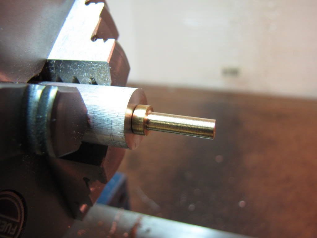
Turned one end down for the handle.
Turned the other end down for a 5-40 thread and chamfered it.
Used my (now trusty) homemade hack saw parting tool to make a thread relief.
Threaded.

Now for the fun part.

Took a piece of aluminum, faced it, drilled, and tapped for 5-40.
Put the crank handle in it. Here’s the pic.

IMG_0460.jpg


Then it was time to file…file….file…file.
Had to be careful. Every once in a while the handle wanted to unscrew itself.
Slow and easy.
It occurred to me that I might have been able to set the compound at an angle and used the lathe to taper. But it wouldn’t have worked unless I did something to ensure the handle didn’t unscrew itself. Either cut from the other side (don’t know how), soldered (but not using aluminum), or loctite or some such. The last two seem a bit much for this tiny handle. Anyway…I was half-way in before I thought about it. Too late to pull-out as they say.

Only lost a bit of thumbnail…nothing was turning…just slipped.

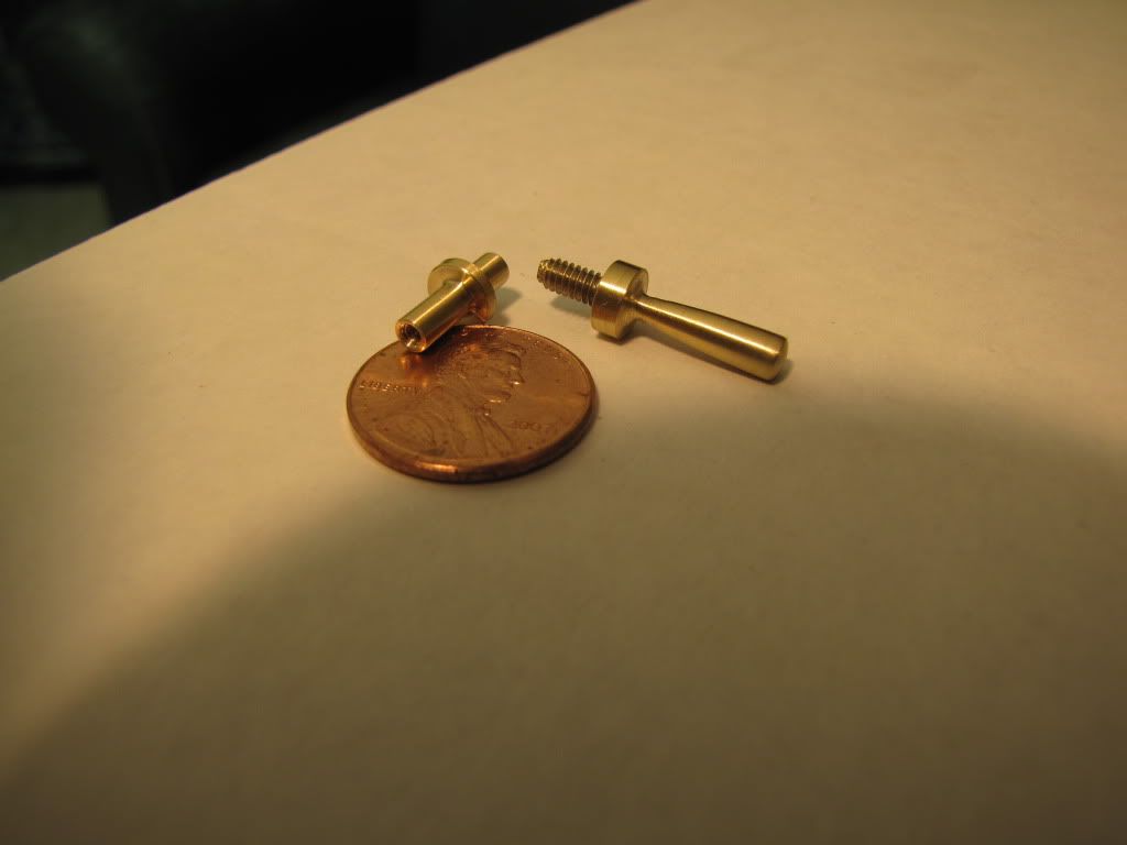
Here’s the result (on the right). (Don't know what that mystery part is on the left.)
Still have to bend it at some angle. Going to wait. I'd rather snap it off later than right after I made it. ;)

IMG_0461.jpg


I think I’m going to name the mill engine ‘Isabella’.

 
zeeprogrammer said:
Made the crank handle anyway.
Turned one end down for the handle.
Turned the other end down for a 5-40 thread and chamfered it.
Used my (now trusty) homemade hack saw parting tool to make a thread relief.
Took a piece of aluminum, faced it, drilled, and tapped for 5-40.
Put the crank handle in it. Here’s the pic.
Then it was time to file…file….file…file.
Had to be careful. Every once in a while the handle wanted to unscrew itself.
It occurred to me that I might have been able to set the compound at an angle and used the lathe to taper. But it wouldn’t have worked unless I did something to ensure the handle didn’t unscrew itself.
Only lost a bit of thumbnail…nothing was turning…just slipped.
Here’s the result (on the right). (Don't know what that mystery part is on the left.)
Still have to bend it at some angle. Going to wait. I'd rather snap it off later than right after I made it. ;)
I think I’m going to name the mill engine ‘Isabella’.


Ha, that's awesome. Apply it to whichever bit you want. Even " I'd rather snap it off later than right after I made it."
Two thumbs up. :bow:

 
That looks great Zee. How far do you have to bend it? As to the mystery part, looks a lot like the crankshaft on the rocker engine....hmmm :)

Bill
 
Good going Zee Thm:
Now don't polish up that "encoding wheel" too much; you'll confuse the optocoupler :big:!
Regards, Arnold
 
Thanks Vernon.

Thanks Bill. Looks like 60 degrees. Wonder if it helps to warm it up a bit?

Thanks Arnold.
 
Zee, heat should help. I might suggest you turn another piece with a shoulder and a diameter similar to that where the handle will be bent and test it that way first. You wouldn't have to put as much effort into the trial part and I would hate to see you break the finished handle.

Bill
 
Back
Top