Honda GX160- 8.5cc

Home Model Engine Machinist Forum

Help Support Home Model Engine Machinist Forum:

This site may earn a commission from merchant affiliate links, including eBay, Amazon, and others.

Basil

Well-Known Member
HMEM Supporting Member
Joined
Mar 18, 2017
Messages
230
Reaction score
346
Location
Dorset UK
Probably biting off way more than I can chew here but I'll make a start and see how far I can get. With my first engine pretty much complete and running (Seal Major 30cc) I'm up for another challenge. I've built 100s of these little Honda engines over the years and have literally thousands of parts around the shop so it was a natural choice for me to contemplate "What if".
After lots of back and forth I've come up with a scale of 2.6 to 1. and have 3D printed this size for evaluation.
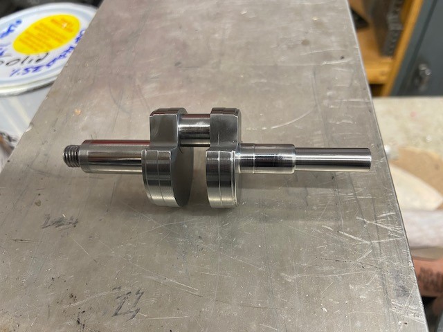
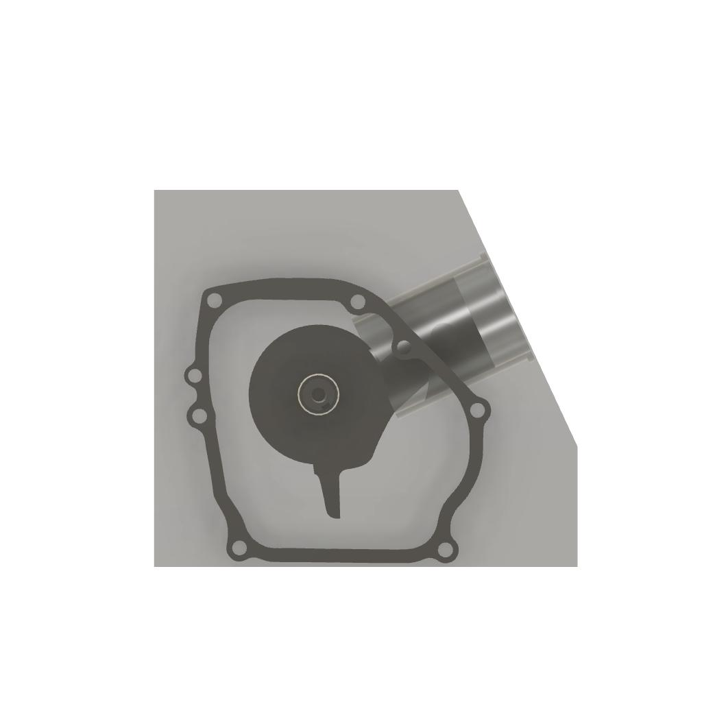
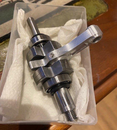
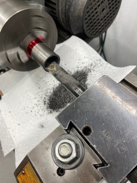
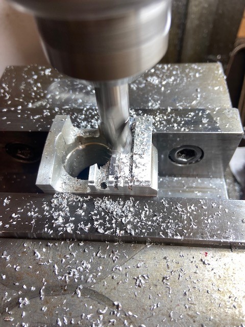
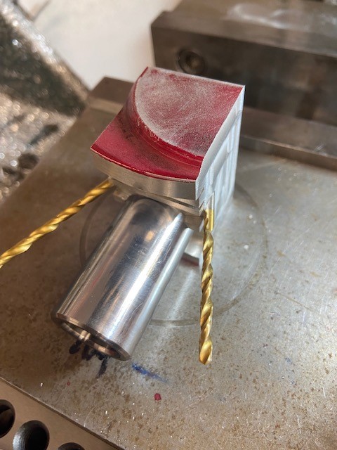
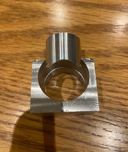
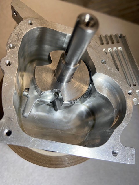
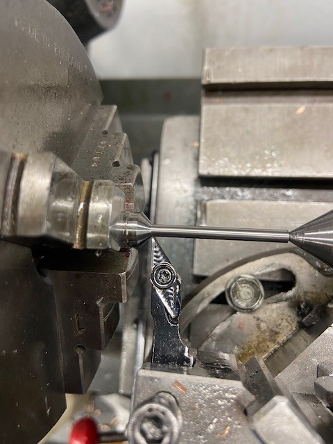
Crankshaft first. I've ordered the metal and started to draw the engine up in Fusion to check for interferences. With slight modifications to account for scaling and the rounding of numbers I'm going to try to keep it somewhat to the original.
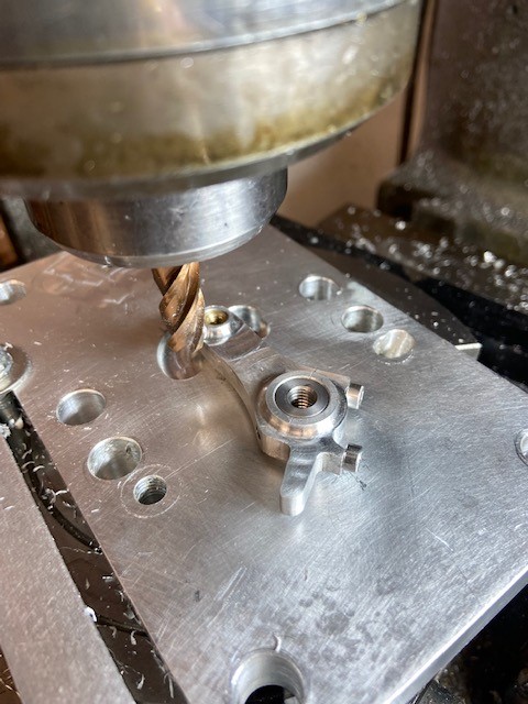
I have no idea how I am going to make many of the components but I'm sure something will presents itself when the time comes and I'll learn lots along the way. Which for me is what it's all about. Wish me luck! And please any advice would be much appreciated. 🍻 👍
 

Attachments

  • IMG_6605.jpg
    IMG_6605.jpg
    124.3 KB · Views: 350
  • IMG_6604.jpg
    IMG_6604.jpg
    118.2 KB · Views: 367
  • 906C6EED-10C2-4A64-82DA-3A69EF2F5E01.mov
    9.1 MB
  • Honda GX160 2.6 Scale v15 (2).jpg
    Honda GX160 2.6 Scale v15 (2).jpg
    96.3 KB · Views: 347
  • Honda GX160 2.6 Scale v15.jpg
    Honda GX160 2.6 Scale v15.jpg
    26.9 KB · Views: 302
Love the idea. I was thinking of something similar a while back, These engines are a proven design, are absolutely ubiquitous the world over and clones/copies abound. Watching with keen interest.

P
 
Cheers. Yes I read somewhere the GX line is the most mass produced and copied engine design in the world.
Got the metal today and I'm looking forward to getting started. Problem is I leave on vacation for 2 weeks in the morning :rolleyes:.
I'll take my notepad and do some planning anyway.
 
Well the first part is made. Connecting rod next!
Crankshaft is from EN24T which did warp slightly after milling the crankpin material down. Had about 7 thou runout. After quite a bit of pressure in the Kurt vice got it to a thou.
Some good use out of my Hemmingway grinder on the rod journal . Modified to take a larger wheel.
Bearings and seals all worked out close to scale. Just need a 2mm key slot in the output shaft and I decided to leave the flywheel taper location until I have a crankcase complete.
Made a start on crank machining for balance but I will wait until the other reciprocating parts are made and then work up a "bob" weight.
 

Attachments

  • IMG_6983.jpg
    IMG_6983.jpg
    118.6 KB · Views: 209
  • IMG_6987.jpg
    IMG_6987.jpg
    80.8 KB · Views: 207
  • IMG_7005.jpg
    IMG_7005.jpg
    95.1 KB · Views: 205
  • IMG_7007 (1).jpg
    IMG_7007 (1).jpg
    126.9 KB · Views: 208
  • IMG_7008 (2).jpg
    IMG_7008 (2).jpg
    113.5 KB · Views: 213
  • IMG_7018.jpg
    IMG_7018.jpg
    110.4 KB · Views: 214
  • IMG_7034.jpg
    IMG_7034.jpg
    96 KB · Views: 225
  • IMG_7035.jpg
    IMG_7035.jpg
    96.3 KB · Views: 243
  • IMG_7037.jpg
    IMG_7037.jpg
    84 KB · Views: 240
Last edited:
Connecting rod done I am moving on to the block. Not having casting facilities or a CNC I've decide to manually carve this. If I can get through this part of the build the project stands a chance of completion. I know its going to be a challenge!
 

Attachments

  • Honda GX160 2.6 Scale v42.jpg
    Honda GX160 2.6 Scale v42.jpg
    31.2 KB · Views: 183
  • IMG_7063.jpg
    IMG_7063.jpg
    114.6 KB · Views: 196
  • IMG_7071.jpg
    IMG_7071.jpg
    89.5 KB · Views: 202
  • IMG_7068.jpg
    IMG_7068.jpg
    149.4 KB · Views: 190
Thank Andy. The crankcase is taking shape, trying to keep it very much like the original with a few deviations to make it more build friendly. Had a little error on the lower fin spacing that broke through to the pushrod area. Luckily I didn't get into this too far and it will be rectified with 2 press in dowels and re-machined. I am going to move onto the liner at this stage so as to get a final crankshaft position in the block that allows the rod to clear best the lower liner area.
 

Attachments

  • IMG_7073 (1).jpg
    IMG_7073 (1).jpg
    103.8 KB · Views: 122
  • IMG_7085.jpg
    IMG_7085.jpg
    115.6 KB · Views: 132
  • IMG_7089 (1).jpg
    IMG_7089 (1).jpg
    97.4 KB · Views: 134
  • IMG_7093.jpg
    IMG_7093.jpg
    96.3 KB · Views: 142
  • IMG_7127.jpg
    IMG_7127.jpg
    115 KB · Views: 133
  • IMG_7125.jpg
    IMG_7125.jpg
    121.8 KB · Views: 134
  • IMG_7116.jpg
    IMG_7116.jpg
    133.6 KB · Views: 131
  • IMG_7120.jpg
    IMG_7120.jpg
    93.6 KB · Views: 127
  • IMG_7094.jpg
    IMG_7094.jpg
    101 KB · Views: 128
Last edited:
Liner is machined from cast iron and finished with the finest stone I have. Will probably wrap a stone with 1500 W/D to get a really smooth finish.
I went on a scrounge for some material to make the piston from. I was not totally happy with the piston material that was used in the Seal Major although it does run well the finish after running looked a little drawn like the aluminum is not hard enough. I have some old big block Chevrolet forged racing pistons and got to wondering if I could find a big enough lump to make this piston. Some hours later with the use of the band saw I had a piece that looked like it could be suitable but with the holes for the wrist pin lube things would be very tight. The piston is 24mm. The forged aluminum cut with a very crisp note which I liked. After machining I'm at 2 thou clearance with a slight additional clearance towards the crown. The last picture is comical with the size of the wrist pin larger than the little Honda piston. Everyone have a great Christmas and don't be tracking the metal shavings in the house. :rolleyes:🍻
 

Attachments

  • IMG_7132 (2).jpg
    IMG_7132 (2).jpg
    105 KB · Views: 115
  • IMG_7135 (1).jpg
    IMG_7135 (1).jpg
    115.2 KB · Views: 119
  • IMG_7137.jpg
    IMG_7137.jpg
    91.1 KB · Views: 122
  • IMG_7138 (1).jpg
    IMG_7138 (1).jpg
    95.2 KB · Views: 121
  • IMG_7141.jpg
    IMG_7141.jpg
    92.1 KB · Views: 119
  • IMG_7143.jpg
    IMG_7143.jpg
    139.4 KB · Views: 116
  • IMG_7146.jpg
    IMG_7146.jpg
    107.9 KB · Views: 119
  • IMG_7148.jpg
    IMG_7148.jpg
    83.2 KB · Views: 127
  • IMG_7150.jpg
    IMG_7150.jpg
    93.3 KB · Views: 122
Last edited:
A little more progress on the Little Honda GX. Carving away at the cover plate with lots more to go. The inner sump with oil fills is complete.
I have decided to go with the Zenoah mag arrangement. I did not want to have a separate battery for ignition. Its going to be very close but when clocked correctly it does fit within the cover geometry. There is a separate coil unit required but I have a plan for this to be hidden within the engine.
 

Attachments

  • IMG_7179.jpg
    IMG_7179.jpg
    115.1 KB · Views: 81
  • IMG_7180.jpg
    IMG_7180.jpg
    124.7 KB · Views: 81
  • IMG_7181.jpg
    IMG_7181.jpg
    138.6 KB · Views: 92
  • IMG_7184.jpg
    IMG_7184.jpg
    104.8 KB · Views: 96
  • IMG_7190.jpg
    IMG_7190.jpg
    147.4 KB · Views: 95
  • Honda GX160 2.6 Scale v59 (2).jpg
    Honda GX160 2.6 Scale v59 (2).jpg
    97.8 KB · Views: 93
Moving along with the cylinder head and coil, stator mods. The Zenoah ignition parts needed some modification, mainly to bring the pickup closer into the stator/ flywheel center. I accomplished this by reducing the size of the stator and carefully!!:oops: machining the legs on the pickup.
Lots of different angles on the cylinder head for ports etc. Some of these were easier to set up when the head is bolted to the cylinder block. The head is now ready for the fins to be cut.
I printed up a couple of pistons for mockup, worked the numbers and machined the head for a 7 to 1 compression ratio, figuring this was a good starting number and could be adjusted on either side as required.
Just received the Phopher bronze for the valve inserts so that's probably next on the list.
 

Attachments

  • IMG_7212.jpg
    IMG_7212.jpg
    90.4 KB · Views: 124
  • IMG_7222.jpg
    IMG_7222.jpg
    107.1 KB · Views: 125
  • IMG_7225.jpg
    IMG_7225.jpg
    130 KB · Views: 117
  • IMG_7231.jpg
    IMG_7231.jpg
    122.4 KB · Views: 123
  • IMG_7256.jpg
    IMG_7256.jpg
    83 KB · Views: 120
  • IMG_7257.jpg
    IMG_7257.jpg
    91.7 KB · Views: 126
  • IMG_7258.jpg
    IMG_7258.jpg
    91.6 KB · Views: 132
  • IMG_7259.jpg
    IMG_7259.jpg
    106.2 KB · Views: 142
  • IMG_7260.jpg
    IMG_7260.jpg
    101.6 KB · Views: 149
  • IMG_7247.jpg
    IMG_7247.jpg
    122.3 KB · Views: 140
Last edited:
lovely job! this engine is the pinnacle of small petrol engines, a modern classic. Look forward to the finished article.
 
Thank you Edi. I ran a Fadal CNC for nearly 20 years and I really am missing it. I'm always looking to see what is available in a smaller format. I have seen some machining centers for good prices but the problem comes when you need a repair. I burnt the spindle up in the Fadal and it cost me $5000.
 
Some more progress on the little Honda. The oil hole for the big end journal which feeds around the rod bolt. Finalizing the work on the piston. Working with the small slug that was harvested from the larger piston presented some issues holding onto it.
I wanted to make the piston pin hardened. I used a piece of water hardening drill rod and tempered it to 260C. With my little hardness files it is still around 60 rockwell which I think should work ok? I ground it slightly oversize and W&D to fit and polish.
 

Attachments

  • IMG_7317 (2).jpg
    IMG_7317 (2).jpg
    104.1 KB · Views: 65
  • IMG_7320.jpg
    IMG_7320.jpg
    122.9 KB · Views: 66
  • IMG_7327.jpg
    IMG_7327.jpg
    119 KB · Views: 64
  • IMG_7329.jpg
    IMG_7329.jpg
    97.9 KB · Views: 62
  • IMG_7332.jpg
    IMG_7332.jpg
    122.2 KB · Views: 65
  • IMG_7334 (1).jpg
    IMG_7334 (1).jpg
    77.5 KB · Views: 67
  • IMG_7342.jpg
    IMG_7342.jpg
    106.6 KB · Views: 66
  • IMG_7344.jpg
    IMG_7344.jpg
    84.2 KB · Views: 66
  • IMG_7346.jpg
    IMG_7346.jpg
    123.5 KB · Views: 63
  • IMG_7345.jpg
    IMG_7345.jpg
    103.3 KB · Views: 62
I decided to go with aluminum pin buttons and machined them to fit the bore contour. I did not get any pics of the making of the valve buckets. They are standard design and machined from Phosphor bronze. Valves are stainless and I machined up a fixture so I can finish the stems to height and machine on the clip grooves. At the beginning of the build I decided to go with a piston ring that was readily available having never made piston rings before I thought I'd leave that for the future. I assembled the bottom end this evening and she turns over nice. It's a tight fit in there! I've also never cut gears before but that seems to be looming on the horizon.
 

Attachments

  • IMG_7350.jpg
    IMG_7350.jpg
    108.3 KB · Views: 66
  • IMG_7349.jpg
    IMG_7349.jpg
    115.4 KB · Views: 65
  • IMG_7351.jpg
    IMG_7351.jpg
    98.5 KB · Views: 67
  • IMG_7354.jpg
    IMG_7354.jpg
    100.6 KB · Views: 68
  • IMG_7270.jpg
    IMG_7270.jpg
    129.2 KB · Views: 68
  • IMG_7286.jpg
    IMG_7286.jpg
    103.3 KB · Views: 68
  • IMG_7290.jpg
    IMG_7290.jpg
    105.6 KB · Views: 71
  • IMG_7314 (1).jpg
    IMG_7314 (1).jpg
    88.4 KB · Views: 74
  • 1CAE6235-9AD4-440A-B34E-7B872CDB7429 (2).jpg
    1CAE6235-9AD4-440A-B34E-7B872CDB7429 (2).jpg
    57.4 KB · Views: 78
  • IMG_7341 (2).jpg
    IMG_7341 (2).jpg
    77.3 KB · Views: 73

Latest posts

Back
Top