Help with valve

Home Model Engine Machinist Forum

Help Support Home Model Engine Machinist Forum:

This site may earn a commission from merchant affiliate links, including eBay, Amazon, and others.

PeterB

Well-Known Member
Joined
Mar 2, 2012
Messages
53
Reaction score
14
Please, help me, I need a brain :-\

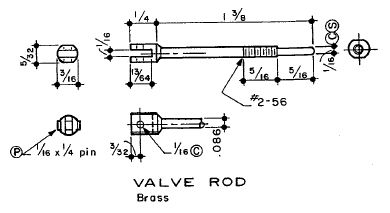
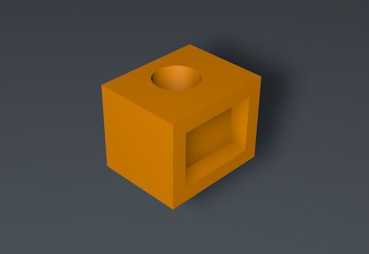
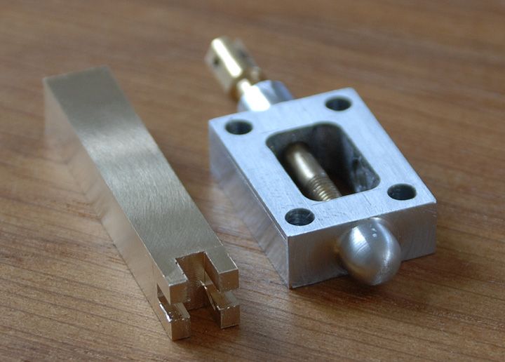
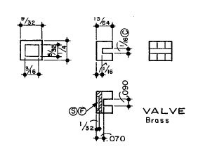
I'm building Elmers Grasshopper engine and the next part I'll do is the valve. But I can't figure out how the valve is designed. Can some smart guy at HMEM please tell me how I should do. I have seen some photos of such a valve but there is always two parts. In the plan I got there is only one part.

valve.jpg
 
Hi Peter,

I have attached a very rough C-o-C that shows what the block should look like when finished. I hope it explains it enough.
But of course, not as big. They are rather small on Elmers engines.

Good luck

John

Valve Block.jpg
 
Great, but how do I connect the valve rod to that valve ???
valve_rod.jpg
 
Pete,

Same as Bogs ;D

Valve.jpg


The Vv rod nut goes in the recess and the rod in the other recess at 900. The steam pressure will hold it on the seat and the rod will be held by the gland packing and I think the 5/16" bit on the end will be a guide for the rod at the other end of the steam chest.

Hope this helps
Best Regards
Bob


Have a look see here - I've put up a 19 pic series on making just such a thing.
 
PeterB said:
Great, but how do I connect the valve rod to that valve ???
valve_rod.jpg

There's a 9/32 x 1/8 x 1/16 M2-56 brass nut on page 168.
Either that or something the like.
Marcello

--
[EDIT] "M2-56" reads 2-56 thread, M2 *may* be what I used.

 
Hi Peter.

On the plans there's a little rectangular item just labeled "Nut" that you have to make - that is the nut that fits into the slot on the top of the valve, and the valve rod screws into it. If I recall correctly, Elmer specified the thread on that nut as "Close".

If you click on the photo below, look around the center to find the valve - the nut is lying next to it:


Kind regards, Arnold
 
WOW, now I see. But is it necessary to mill that "cross"? What do you think about to just drill and tap a hole instead?
Shouldn't that work the same way?
valve_2.jpg
 
mzetati said:
There's a 9/32 x 1/8 x 1/16 M2-56 brass nut on page 168.
Either that or something the like.
Marcello

Fantastic, I think I need a new pair of glasses :p
 
Hi Peter.

No, drilling and tapping the valve itself will not work; the valve must be able to "float" on the valve rod, as it needs to be pressed against the valve plate by steam (air) pressure.

Kind regards, Arnold
 
I'll tell you guys - this forum is really great.
Thank you for all help. Now I understand how the valve works and what it would look like.
I'll tell you, it's much more fun to make all the engine parts when I understand the functionality :bow:

Now I can go on with my Grasshopper :)


Thanks
/Peter
 
Ya beat me to it Arnold!

Yeah, typical of Elmer's drawings, the nut is not shown where you would expect it, but buried deeper into the drawings.


grasshopper nut.jpg


grasshopper nut.jpg
 
arnoldb said:
Hi Peter.

No, drilling and tapping the valve itself will not work; the valve must be able to "float" on the valve rod, as it needs to be pressed against the valve plate by steam (air) pressure.

Kind regards, Arnold

YEP!
A "push fitting" nut implies dismounting the valve once again and a little filing.
Been there, seen that.
Marcello

 
Now, I'm on the way...
I've just begin to mill the valve. Hera is a pic of the little brass bar and the steam chest :)
There is just one thing I don't like, and that is the size of the small parts. My machines is good enough to handle the small pieces but I and my eyes have some problem :-\

/Peter

valve-and-steam-chest.jpg
 
As mentioned the valve must be free to float so as to make good contact with the valve port face , but there is a second reason.
If used under steam water will be condensed in the cylinder until operating temperature is reached .
Unless drain cocks are fitted , quite fiddly in small engines , then the only way for this condensate to leave the cylinder is via the slide valve which is lifted off the port face by the piston attempting to compress the liquid.
Where slides are used such as a port face and slide valve it is good practice to use dissimilar materials , on a brass face the valves are usually gun-metal (red brass)
In my own engines I use graphite filled PEEK for the valves , this has a very low co-efficient of friction and wears very well.
 
A very good point Abby regarding lifting of the valve for a slug of water. In regards to carbon filled Peek, sure, that'll work, but it is a bit pricey unless you have a supply from the "skip"/dumpster.

I've had very good luck with Iron on Iron and with Brass valve on a lapped stainless steel port plate.

If your only running on air of about 60 psi or less....the options are really wide open...Nylon would work fine for a valve against Aluminum or just about anything else.

Dave
 
well ther you go. I was stuck on a similar problem with an engine I have on the backburner for now. Just could not get my head around it and now so simple ....Gotta love this forum.
 

Latest posts

Back
Top