Help with screw cutting on a myford

Home Model Engine Machinist Forum

Help Support Home Model Engine Machinist Forum:

This site may earn a commission from merchant affiliate links, including eBay, Amazon, and others.

firebird

Well-Known Member
Joined
Oct 26, 2007
Messages
1,143
Reaction score
8
Hi

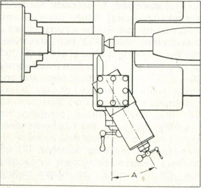
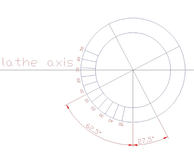
I need help (in more ways than one but I won't go into that just now) with screw cutting.
I'm trying to cut a 12TPI thread, same as Myford nose thread. I have the Myford owners hand book which I have studied and think I understand what to do. The bit I'm not sure about (the book isn't too clear on this) is setting the top slide over to 27 1/2 degrees. The markings on the top slide scale don't go far enough and I don't think it will turn far enough anyway.


What am I missing here?????

Cheers

Rich
 
Your just missing a little bit. If you position the compound screw in line with the crossfeed screw, you will see that the "0" mark on the compound degree scale aligns with a wisdom mark on the crosslide. Now move the compound in the direction shown in your photo so that you are about splitting the 27/28 degree marks. In other words as shown it your photo you are too far already, your about 45°

Your cutter must be ground at 55° not the more common 60°. You will need to practice with a bunch threads before you tackle a backplate for your Myford. I'd suggest that since your Myford has a 8 pitch leadscrew, practice with 24 tpi first, then 16, then 8. When comfortable with those, then move to 20 then 12. Crawl, walk run.

You need to reset the position of the T-Bolts to lock the compound into the correct position.
 
It's a crappy angle markings on the topslide that are confusing you ...
ML7 topslide can rotate about 63deg, so no problem in setting over as required.
Your topslide looks about right.

Chris

ps this has been discussed before ;)
Here is the angle you are looking for:
img135.jpg

 
Hi

Thanks to everyone, be patient with me.

I have just nipped out to the workshop and set the top slide on the 27 1/2 mark

DSC00745.jpg


Is that right? The reason I am questioning this is the drawing in the myford book makes the top slide look much further over like the drawing from Chris.

Cheers

Rich
 
you have gone to far, you should be reading 601/2 on your dial you are closer to 45. you just went to far. jonesie
 
Hi

I think I'm getting what you all mean but I'm still struggling somehow.
Machinetom said

If you position the compound screw in line with the crossfeed screw, you will see that the "0" mark on the compound degree scale aligns with a wisdom mark on the crosslide.

You can see from this photo that I can't swing it round far enough to align the screws, they foul each other?


And if I could swing it that far the mounting studs won't align with the T slots.


Cheers

Rich
 
Hi again

I think I've got it now. Studied and re read everything and thanks to Chris as well for his sketch :wall: :wall: :wall: :wall: :wall:

[ame]http://www.youtube.com/watch?v=n0sLVkcQVz8[/ame]

You know sometimes you just can't see it can you then finally the penny drops.

Cheers

Rich
 
As Henry Higgins once said "By George you've got it" Does that make me sound OLD?


On the Super 7 they got rid of the Too large flange and hold down bolts, now the numbers are so small you need a dang magnifier to read them, the witness marks less than.100 in lenght. But an improvement from the ML7.
 
Hi

By George I have got it woohoo1 Thm: Thm: Thm:

After a couple of practice goes I did what I wanted to do and that is to put a 1 1/8 x 12 TPI thread onto the end of a R8 - 2MT adapter so I can now use my Myford collets and closing ring in my X3 mill


Cheers and many thanks to all those that helped :bow: :bow: :bow:

Rich
 
By George he's got it! You did a nice job of it Rich.
 
Hi Tel

Thanks, screw cutting is a big feather in my cap. It ain't as scary as I imagined it would be. I took it real slow and careful, in slowest back gear and it came out really well.

Cheers

Rich
 
Thats a good looking thread. Well done, If you haven't as yet you should get a set of thread measuring wires. The only way to know the results are to size without fitting its mating part. The wire kits are resonably priced.
 
Well done Rich Thm:, Congratulations! That thread came out looking great!

The 1 1/8th x 12 TPI is a fairly coarse thread - if you can do that one as well as you have, you'll find finer threads a lot easier to do, and very useful indeed ;)

I find screw cutting easier than parting off - even though I don't use the offset method - and it is a particularly satisfying job to do on the lathe; I actually enjoy it.

Looking forward to your first internal thread now Thm:

Kind regards, Arnold
 
Hi

Thanks Tom and Arnold.

Internal threads will have to be cut on a project I have in mind, I'll keep you posted.

Cheers

Rich
 
Hi Rich,
Congratulations on getting it right, making a very good looking thread, but all that palaver with the top slide setting is really not necessary as you will find as you get more experience.
If you are getting the "bug" for threading, make yourself one of "Bog's" clapper box thread cutting holders, they are the greatest improvement in threading since the invention of the electric motor. I made one to take carbide thread cutting inserts and would not willingly give it up.
Ned
 
Hi Ned

Thanks.

I tried a search for clapper box thread cutting holders but couldn't find it, have you got a link to it???

Cheers

Rich
 
Hi Rich,
Arnold beat me to it. As for, Arnold never mind about a "to do" list get on and make one, you wont regret it.
If anyone is interested, the inserts that I am using are Glanze partial form Metric inserts, by which they mean that it only cuts the valley. If you have full form inserts they cut the crests as well but you need a different one for each pitch, and that can get expensive.
So far I have cut 0.75mm through to 1.5mm threads, some times I don't even get a burr on the crests, when threading Stainless.
If there is one disadvantage of the clapper box device, it is that you need to put a run-out groove in the work piece, which can look very amateurish. You can of course use the threading tool to create the groove, instead of a parting tool as I have seen some people use.
I already have two different types, the other takes an Ifanger style insert, but I am tempted to make John Stevenson's version using Coventry die head inserts, for Imp threads, as shown on his video. [ame]http://www.youtube.com/watch?v=6TR0ssQrmI8[/ame]
You can never have too many tools,can you?
Ned
 
Back
Top