Tony Bird
Senior Member
Hi,
In another thread I mentioned hand cutting a slot for an '0' in a piston and someone asked how this was done in metal? As others might be interested and I have just fitted two '0' rings to another piston using the same technique I took some photographs which might explain the way I do it.
I first used a lathe when I was in school in a metalwork class I think it was a Myford ML7. When I left school I became an apprentice in the watch, clock and jewellery repair trade and for the next 5 years I only used lathes fitted only with a 'T' rest
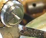
1. The 'T' rest on my Boley Leinen watchmakers lathe it is hinged so it can be moved out of the way for measuring.
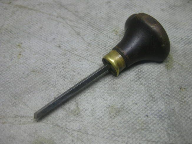
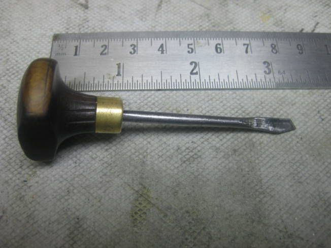
2. The most commonly used hand turning tool for metal, a graver with a lozenge shaped end.
3. A 'T' rest I made for my Myford Super 7B along with a commercially made 'T' rest I bought second hand which is used for both wood and metal.
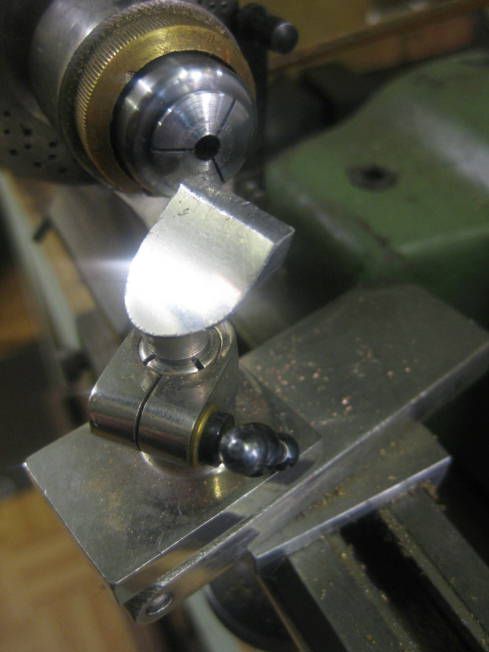
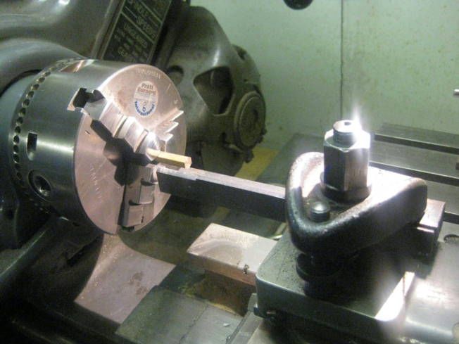
4. A homemade rest that fits in the tool post.
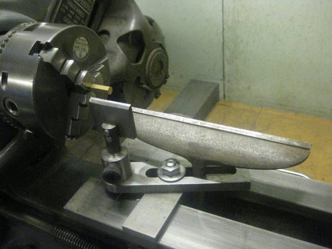
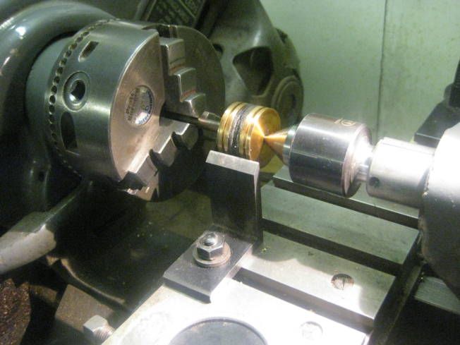
5. The piston from an old model steam locomotive which is to have two '0' rings fitted. The '0' rings are Viton with an OD of 1.25" and an ID of 1".

6. The graver to be used is for parting off, it is made from a piece of flattened silver steel which has been hardened and tempered.
7. The 'T' rest to be used is home made from a piece of angle, the usual tool post has been removed from the cross slide. The slots in the piston were made using a parting tool.
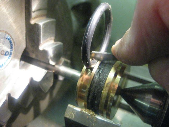
8. The graver is being used to widen the slot.
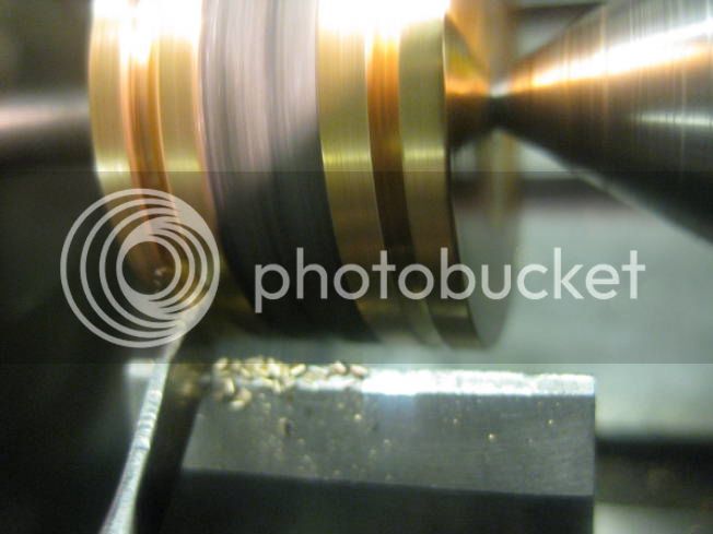
9. The slot is now wide enough so the '0' ring fits so it doesn't touch the sides of the slot.
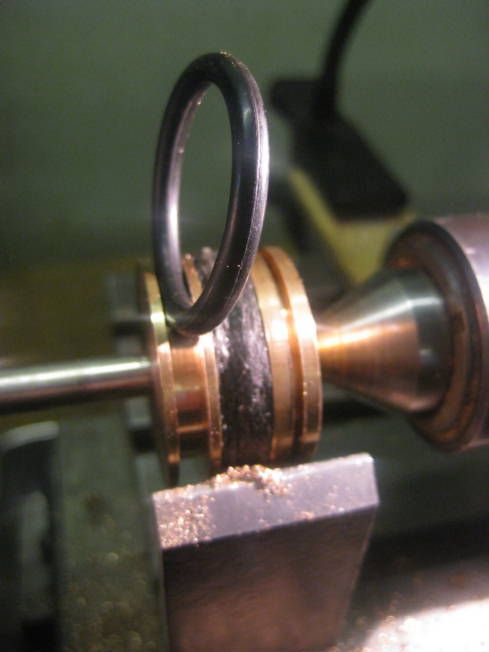
10. The slot is now just deep enough so the '0' ring can be revolved under the graver resting on the piston.
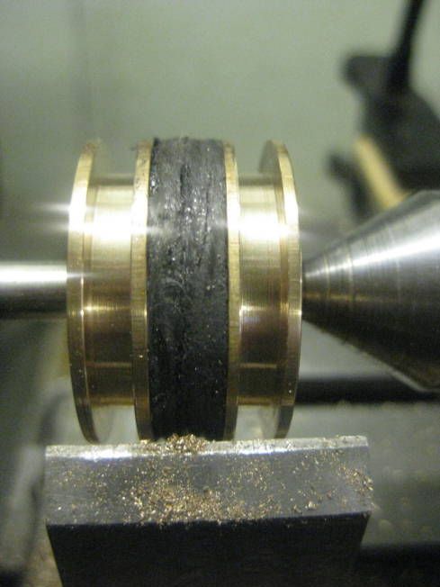
11. The two slots finished and ready for '0' rings to be fitted.
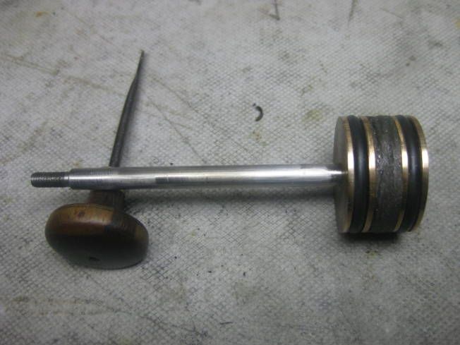
12. Finished. If the '0' rings are fitted correctly they should just revolve in their slot in the piston.
If you have hand turned wood turning metal is just the same, place the 'T' close to the work piece and present the tool just below the centre line just as a fixed tool would be set. You use both hands and have to press quite hard especially when turning slots. Brass and bronze are reasonably easy to turn steel needs a lot of pressure. I don't know about aluminium I haven't hand turned it. I do a lot of hand turning as it is quick and needs little set up and puts less load on the work piece than using a fixed tool. Most of the jobs are cosmetic fancy shapes and the like, I will try and find some photographs and post them. I have friends who come to my workshop and play once a week and several of them hand turn very well after only an hour or so playing. Like using fixed tools it works better if the tools are sharp!
If there is something that isn't clear please ask.
Regards Tony.
In another thread I mentioned hand cutting a slot for an '0' in a piston and someone asked how this was done in metal? As others might be interested and I have just fitted two '0' rings to another piston using the same technique I took some photographs which might explain the way I do it.
I first used a lathe when I was in school in a metalwork class I think it was a Myford ML7. When I left school I became an apprentice in the watch, clock and jewellery repair trade and for the next 5 years I only used lathes fitted only with a 'T' rest
1. The 'T' rest on my Boley Leinen watchmakers lathe it is hinged so it can be moved out of the way for measuring.

2. The most commonly used hand turning tool for metal, a graver with a lozenge shaped end.

3. A 'T' rest I made for my Myford Super 7B along with a commercially made 'T' rest I bought second hand which is used for both wood and metal.

4. A homemade rest that fits in the tool post.

5. The piston from an old model steam locomotive which is to have two '0' rings fitted. The '0' rings are Viton with an OD of 1.25" and an ID of 1".

6. The graver to be used is for parting off, it is made from a piece of flattened silver steel which has been hardened and tempered.

7. The 'T' rest to be used is home made from a piece of angle, the usual tool post has been removed from the cross slide. The slots in the piston were made using a parting tool.

8. The graver is being used to widen the slot.

9. The slot is now wide enough so the '0' ring fits so it doesn't touch the sides of the slot.

10. The slot is now just deep enough so the '0' ring can be revolved under the graver resting on the piston.

11. The two slots finished and ready for '0' rings to be fitted.

12. Finished. If the '0' rings are fitted correctly they should just revolve in their slot in the piston.

If you have hand turned wood turning metal is just the same, place the 'T' close to the work piece and present the tool just below the centre line just as a fixed tool would be set. You use both hands and have to press quite hard especially when turning slots. Brass and bronze are reasonably easy to turn steel needs a lot of pressure. I don't know about aluminium I haven't hand turned it. I do a lot of hand turning as it is quick and needs little set up and puts less load on the work piece than using a fixed tool. Most of the jobs are cosmetic fancy shapes and the like, I will try and find some photographs and post them. I have friends who come to my workshop and play once a week and several of them hand turn very well after only an hour or so playing. Like using fixed tools it works better if the tools are sharp!
If there is something that isn't clear please ask.
Regards Tony.