Hall effect woes!

Home Model Engine Machinist Forum

Help Support Home Model Engine Machinist Forum:

This site may earn a commission from merchant affiliate links, including eBay, Amazon, and others.
Hi Luc,
Yes, very interesting and explains very well.
The early bits a little basic but that's a great way to intro anyway. The latter half I find very interesting and have it on my tablet now so can peruse at leisure.
I have done some electronics in the past but am only a dabbler so any education to this 57yr brain is welcome.
Many thanks.Thm:
Rich

Good news ;)How do you like the book I posted

cheers
 
jerrybilt:

You are correct about the resistor on the gate of the FET. I was looking right through the FET as if the resistor were connected to the coil. Sort of "not seeing the forest for the trees" as it were. Not sure What I was thinking.

Most important:
In your most recent post you have eluded to some conditioning on the input signal that will always reduce it to a single pulse per trigger input and no possible steady state high DC level. Is that correct ??

Again, no suggestion of that was given originally (or I missed it), so my analysis of the circuit was only based on the circuit driven by points or a hall sensor.

No consideration was given (or suggested) originally that it was intended to operate in more of a switching power supply type of mode. I certainly didn't recognize it.
That requires a whole different consideration. In that light the inductor placement and a lot of my previous comments go out the window.

Sorry I was jaded by the previous "simple" designs (including my own). I can see now that your circuit is quite a bit more sophisticated.

As for your other comments on timing etc., you have the benefit of having some values in mind for the components and can therefore predict timing etc. You supplied none for our benefit. So I can't add anything in that respect.
I was looking at the whole thing as a linear circuit like the other circuits here.

So I guess I'm looking the fool here for making some of my comments on that basis :(
Oh well.

Have you modeled it in SPICE or any such program?

So, go ahead and build it and report back.
We're all looking for the "ultimate" circuit.

Sage
 
For your consideration:

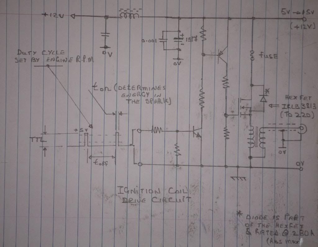
Here is an ignition transformer drive circuit based on a commonly available HEX FET. The input is a standard TTL input and the pulse width is set by a monostable multi-vibrator (how ever one cares to implement it!). This is a "circuit fragment" where I have not calculated the component values as I wish to show what the circuit looks like.

Ign_drive_2_zps4674ab5e.jpg


Jerry,

I've been scratching my head for the last few days. In thinking about your circuit, when the MOSFET turns on, the source pin will go to roughly 12V (12V-I Rds(on)). That said, I can't see how you will maintain enough Vgs to keep the FET on. It is an N-channel FET right?

What am I missing here? I can see your circuit having some possibilities if some kind of high side gate driver IC were used (say the IR2113) to create a charge pump generated gate supply referenced to the source...

John

Am I missing something here
 
John:

That was one of my comments as well back a bit. But he assured us that it will have an excess of drive. Maybe I don't see it.
As you say. The gate voltage is always going to be some fraction of the supply due to the resistor divider. If the source is supposed to go as high as the supply to fully energize the coil then the gate is going to have to be above the supply rail. Being that the FET is apparently a logic level device I guess the gate would need to go at least 2.5v above the supply rail.
Sorry to repeat what you just said.
Can't see see it. No values to do any math. Maybe I'm looking at the static circuit and missing some sort of effects due to switching and the inductor or who knows what.

:confused:


Sage
 
Hi John,

The source voltage will be lower than the gate voltage. Explaining common source configurations is similar to explaining common collector or emitter follower configurations - they should never work! And yes the IR 2113 is a good choice.

Yes this is an n channel enhancement mode fet ... And for old timers it is biased more like a valve then a bipolar transistor, voltage driven as opposed to current driven.

Hi Sage,

Not to worry ...we all have our moments!!

Re: Spice. I do not have anything like that on my home computer though, many moons ago, I used it to test various circuit designs ... mainly front end very low noise amplifiers and a few broad band distributed amplifiers.

Drive? Oh wow! Lots was not said as I wished only to present a circuit form. I would not refer to this as the " ultimate circuit" because this appears to be what " falls out " nothing more nothing less.

If one holds the input high then the fuse blows.

The hall effect sensor will produce a pulse when the magnet passes the sensor. This is where the original pulse comes from ... Every thing is pulses from here on and it makes life so much easier. The Hall device is an analog device so one would amplify this signal suitably and clean up this pulse with a Schmitt trigger. This arrangement provides a timing edge and a pulse with a suitable level ... TTL levels. We now have a timing edge and the pulse width will be determined by the width of the magnet, sensor size and engine RPM. This pulse would be suitable to drive the coil but if it is too broad the spark energy may be higher than required and the battery drain will be higher. What we can do now is control the pulse width ( mono- stable multivibrator) and use a second one to produce a variable delay to adjust the timing advance ( a single, dual, edge triggered mono will do the job) . With this arrangement one would place the magnet in advance of TDC and fine tune the timing electronically - so much easier.

My apologies for not providing component values as I only wished to present an alternative ( among many arrangements). OK I will do some calcs and get back to the discussion. Perhaps I'll have a working prototype for your consideration. This will be my evening job!

Jerry.
 
Thanks for that Jerry:

So it's not some sort of mysterious switching supply sort of mode relying on the inductor??
I'll take your word on the FET driving.

But maybe you can go back to my original comments about the power supply confusion. The left and right sides elude to different supplies yet they are joined together with the connection between the fuse and the signal transistor. The right side apparently variable and the left fixed to 12v.
Sorry if I missed the explanation of that.

Sage
 
Gentlemen do a favour to all the persons following post a favour :(

Before posting a circuit that you're not 100% positive about the good

operation , build it assemble it simulate it and then post it only if it works other wise go back to the drawing table:fan:

If your posting one and you know it is 100% functional in YOUR

APPLICATION then the readers should read all the line's before commenting

about it

cheers
 
Jerry, I just simulated it in spice. It works, sort of. What happens is this:
1) The gate goes high and turns the FET on.
2) The coil starts to charge a bit, then the fact that the source (the side connected to the coil) goes high, there is insufficient Vgs to keep the FET on.
3) This cycle repeats until the hall untriggers.
4) The frequency is dictated by several things like total gate charge and the time constant of the coil.

The neat thing that happens is you'd get multiple sparks!

The bad thing that happens is sure to blow the FET. The voltage at the top of coil (at the source pin) spikes negative (as would be expected). But, the gate is high. I'm seeing negaive Vgs spikes of 50-60 volts with a 1mH coil. This is absolutely positively going to cause gate rupture in the FET.

If this were a P-channel FET, the story would be different, although your input circuit would have to change a bit.

You can simulate it for yourself using LTSpice. It's a free spice tool put out by Linear Technology and can be downloaded from here: http://www.linear.com/designtools/software/#LTspice

BTW, I handed the schematic to one of my EE coworkers (a super smart dude) and asked him simply if he thought this would work. He didn't do a spice simulation but predicted a result that matched the simulation I ran!

I really think your idea has merit but needs some tweaks. The MOSFET approach has some distinct advantages and I would love to see it pursued.

I think it needs either a P-channel for the MOSFET and a zener clamp for the gate, or a floating high side gate driver. Another thought would be a small gate drive transformer like the switching power supply guys use. The cool thing with the transformer or floating gate driver is that, inherently, the coil would never be able to get stuck on.

John
 
Gentlemen do a favour to all the persons following post a favour :(

Before posting a circuit that you're not 100% positive about the good

operation , build it assemble it simulate it and then post it only if it works other wise go back to the drawing table:fan:

If your posting one and you know it is 100% functional in YOUR

APPLICATION then the readers should read all the line's before commenting

about it

cheers

Luc,

What wrong with posting our ideas to subject them for criticism? That way we all learn, and don't end up making potentially disasterous or safety mistakes that cost us a project, money, or an eye. But, most importantly, there is a fine line between constructive and informative criticism and just plain being arrogant and/or condescending. I'll admit I cross that line more than I'd like, but those who know me either ignore it or tell me John, you're doing it again...:p

This holds true for our engine designs, machining techniques, as well as electronics. It's a forum for those who have a common interest. There are those who know more about certain things, those who know a lot about everything, and newbies alike. That's life. But we wouldn't be here unless we either knew the stuff or want to learn more. Right?

I followed this process with my circuit and got a lot of good feedback. (BTW, my circuit works in real life. I'm working with Dsage on the side to come up with a super reliable, yet simple, high performance coil driver).

All in all, Jerry may be right and the circuit will work. In that event we all learn something. I don't think he ever posted with the intent of forcing his idea down our throats and saying this is the right way. My impression is that he had an idea and wanted to share it with us all and get our comments? What's wrong with that?

I'm guessing we just have some basic philosophical differences. Either that, or nobody on earth knows electronics better than you do... I think it's all philosophy...

Cheers,
John
 
Either that, or nobody on earth knows electronics better than you do.

maybe your right on this one:rolleyes: but a **** happen to bad if you feel this way :)
just realize you di Hi jack someone else's post that started wit a regular Hall sensor problem
and now we are at the 4th diagram, that came from another post and you're arguing about a new one.
It would be simpler start a new post and call it ignition circuit this way everyone would know what to expect
 

Latest posts

Back
Top