Hall effect woes!

Home Model Engine Machinist Forum

Help Support Home Model Engine Machinist Forum:

This site may earn a commission from merchant affiliate links, including eBay, Amazon, and others.
So will there ever be a circuit posted on this site that will work AND everyone will agree upon ?? I'm seriously just asking.. Everytime this type of thread gets started it just turns into a "that wont work do it this way" thread.. I can appreciate everyone's take on doing things and I know there are several ways to skin a cat.. But with the electronic knowledge on here it seems everyone could agree on a circuit.. Maybe everyone post thier version of the PERFECT circuit and then put them together and come up with the holy grail of ic circuits.. Thanks..Bill


Bill,

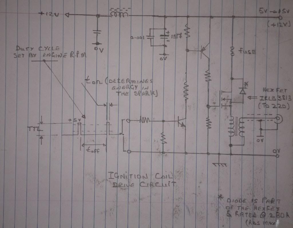
I think Sage's circuit is just that. It's very simple, yet it works and works well. While mine has more protections against power transients and such and lower "standby" power consumption, it is more complicated as a result.

All that said, it holds no advantage over Sage's with regard to its primary purpose... Driving a coil to make a spark and preventing the coil from being stuck on.

So, where are we at? Here's my OPINION FWIW:
If you like soldering up components, or are concerned about power consumption, or want a "Cadillac" circuit, build mine. If you want a good circuit to generate a spark, with "no muss or fuss", build Sage's. You can't go wrong either way.

Bear in mind, though that in Sage's circuit, the LED should not be omitted without fully understanding that the LED and resistor are also being used cleverly as a pullup for the hall sensor - a necessary thing.

Also, either circuit will accept input from a oscillator circuit (or a micro) to make a true multiple spark ignition circuit or to implement your own advance/retard. That's cool stuff on a model engine to be sure!

Now, if you search around the net for model engine ignition circuits, you'll find a few. Some of them are exceedingly bad... I'll hold my tongue about which ones in particular...

John
 
Thanks John:

And, I can give a vote of confidence for John's circuit.
I suggest everyone build his circuit.
There is nothing wrong with adding any of the extra components he has added. Certainly, adding the resistor and capacitor on the Hall power lead adds some protection against spikes on the power line if you're using the same 12v as the coil especially if you have have wiring issues. I haven't had any problem without them. But better safe than sorry though (apparently).

BTW. If you want to be really safe, run the front end on 5v and make +VE 5vdc. Then you'd need to add a regulator etc. but you'd be sure there are no spikes coming from the 12V supply. That's why I designed with the logic level IGBT instead of a darlington transistor. I intended to make another micro driven ignition but decided it wasn't worth the effort for the engine I was putting it on.
http://davesage.ca/engine14.html
Although as I mentioned I did make a multi-spark ignition with a 555 timer because this engine is pretty sketchy about running at all since it's made from plumbing fittings and has nothing for a carb except a big drip oiler. (yup it'' for gas, not oil just like Henry designed it). You can watch it running with the button there on the page somewhere. Wait a bit it takes some time to load the movie.


The Atkinson engine on my site also has a multi-spark ignition of my design but it does use a microprocessor with hall sensor. The micro also also takes care of charging the NiMh battery when you plug in a wall wart. All of the circuitry is flat and hidden under the base plate in less that 1/2" height. You can see the switch, LED and charging socket sticking out the side underneath.

http://davesage.ca/engine3.html


Have fun.

Sage
 
Hi Sage,
Firstly, apologies for not linking to the other thread, I am a bit new to this forum thingy.
I did eventually post a link to it since I knew it was on here somewhere but tricky to find again.
Having run your circuit with Johns mods for two hours @750 rpm via a dc motor, all is fine. I am using common 12V and an auto coil.
I agree that maybe I had done something wrong to cause my initial failures, 3 halls down, but I couldn't figure what was going wrong.
Johns mods seem to work so far, or maybe I am being a bit more careful now? It is true that earth points are critical, I once forgot to add one and saw arcing from the Hall legs to the block! Luckily, that didn't result in death of the semiconductor! :)
This is my first foray into IC engines and it has taken me an age to get the thing running.
[ame]http://www.youtube.com/watch?v=iuXz7O1Ul8g[/ame]
Ultimately, I would like a very small ignition module to build into the base, but I guess this may need a custom coil or higher drive voltage to a ferrite ignitor type coil.
Anyway, thanks to all involved in this thread. It has been very useful to me.
Rich
 
Hi Sage,
Firstly, apologies for not linking to the other thread, I am a bit new to this forum thingy.
I did eventually post a link to it since I knew it was on here somewhere but tricky to find again.
Having run your circuit with Johns mods for two hours @750 rpm via a dc motor, all is fine. I am using common 12V and an auto coil.
I agree that maybe I had done something wrong to cause my initial failures, 3 halls down, but I couldn't figure what was going wrong.
Johns mods seem to work so far, or maybe I am being a bit more careful now? It is true that earth points are critical, I once forgot to add one and saw arcing from the Hall legs to the block! Luckily, that didn't result in death of the semiconductor! :)
This is my first foray into IC engines and it has taken me an age to get the thing running.
http://www.youtube.com/watch?v=iuXz7O1Ul8g
Ultimately, I would like a very small ignition module to build into the base, but I guess this may need a custom coil or higher drive voltage to a ferrite ignitor type coil.
Anyway, thanks to all involved in this thread. It has been very useful to me.
Rich


Nice work on the motor. :D If your interested in electronic I did put a book in the download section that can be download to PDF that book will answer almost all your needs are in electronic

enjoy
 
Hi Sage,
Firstly, apologies for not linking to the other thread, I am a bit new to this forum thingy.
I did eventually post a link to it since I knew it was on here somewhere but tricky to find again.
Having run your circuit with Johns mods for two hours @750 rpm via a dc motor, all is fine. I am using common 12V and an auto coil.
I agree that maybe I had done something wrong to cause my initial failures, 3 halls down, but I couldn't figure what was going wrong.
Johns mods seem to work so far, or maybe I am being a bit more careful now? It is true that earth points are critical, I once forgot to add one and saw arcing from the Hall legs to the block! Luckily, that didn't result in death of the semiconductor! :)
This is my first foray into IC engines and it has taken me an age to get the thing running.
http://www.youtube.com/watch?v=iuXz7O1Ul8g
Ultimately, I would like a very small ignition module to build into the base, but I guess this may need a custom coil or higher drive voltage to a ferrite ignitor type coil.
Anyway, thanks to all involved in this thread. It has been very useful to me.
Rich


Rich, she looks great!

John
 
Having run your circuit with Johns mods for two hours @750 rpm via a dc motor, all is fine. I am using common 12V and an auto coil.
Rich

Hi Rich:

Glad to see you got it going. Are you saying you had the engine and therefore the ignition operating by turning the engine over with a motor? Or was it running on it's own? (i.e. fuel, ignition etc.). Sounds like it was firing so I assume the latter.

Is that the coil I see in the background connected by long lengths of wire and what looks like regular wire on the HV lead tangled amongst them?
And perhaps the long Hall sensor leads in the foreground?
If so then I'm not surprised you've had problems (and that they were solved by filtering the supply). Frankly I'm surprised you still don't have issues.
Hopefully I'm wrong on that observation.


BTW nice machine work. It looks familiar, what is it a model of?

Sage
 
Sweet runner rich.. very nice build. congrats on getting it running.. There is so much smart on here its crazy, I knew they would get you running... Hmmmm if i could get a thimble full of smart from everyone on here, I could be a genius... And learn to spell correctly lol...Bill
 
Rich, she looks great!

John


John: et. al.

I get a real chuckle sometimes at the advertising that gets inserted into posts here. I assume they are different every time one has a look at the site and they are probably tailored to something in the message content.
In any case you replied to the picture of the engine

"She looks great"

When I looked at your response right below it was an ad for a dating service with a pretty nice looking girl. I thought that perhaps you were making a comment and a joke at the same time. Now, I don't see that ad anymore attached to your response. Then the light went on as to what was going on.
I'm sure nobody else saw the two together like I did but now I have to LOL big time.

Too funny.


Sage

Now that is funny! I was, however, commenting on the engine. The girl never popped up on my screen, so I can't comment Rof}

The weird thing is I used to see ads on this site, but now I never see any. The one that annoyed me was a bogus "You've been unfriended by 3 people."

John
 
Yes.
I'm not sure what triggers them. At the moment I don't see any, anywhere. But occasionally they seem to get attached to numerous posts per page. Sometimes they are little semi-transparent rectangles with a message - no picture and they always seem to land at the bottom and obscure a picture. Sometimes I have to "X" them off to get them out of the way.
The price we pay I guess.

Sage.
http://davesage.ca
 
For your consideration:

Here is an ignition transformer drive circuit based on a commonly available HEX FET. The input is a standard TTL input and the pulse width is set by a monostable multi-vibrator (how ever one cares to implement it!). This is a "circuit fragment" where I have not calculated the component values as I wish to show what the circuit looks like.

Ign_drive_2_zps4674ab5e.jpg
 
Hi Sage,
I tested the circuit using a DC motor on its own whilst working on the engine.
The youtube clip is running without the regulator mechanism but it sounds like a hit and miss even then. LOL! I guess its down to valve bounce or something. Still have work to do to get it running correct and some polishing up.
Yes, I am guilty of using the long leads etc and not proper HT lead yet so slapped wrists for me being impatient :eek:. I duly take note of your comments and will improve the setup accordingly.
The engine is a David Kerzel design
www.floridaame.org/GalleryPages/g1h0106.htm

Cheers
Rich

Hi Rich:

Glad to see you got it going. Are you saying you had the engine and therefore the ignition operating by turning the engine over with a motor? Or was it running on it's own? (i.e. fuel, ignition etc.). Sounds like it was firing so I assume the latter.

Is that the coil I see in the background connected by long lengths of wire and what looks like regular wire on the HV lead tangled amongst them?
And perhaps the long Hall sensor leads in the foreground?
If so then I'm not surprised you've had problems (and that they were solved by filtering the supply). Frankly I'm surprised you still don't have issues.
Hopefully I'm wrong on that observation.


BTW nice machine work. It looks familiar, what is it a model of?

Sage
 
For your consideration:

Here is an ignition transformer drive circuit based on a commonly available HEX FET. The input is a standard TTL input and the pulse width is set by a monostable multi-vibrator (how ever one cares to implement it!). This is a "circuit fragment" where I have not calculated the component values as I wish to show what the circuit looks like.

Ign_drive_2_zps4674ab5e.jpg


Jerrybilt:

Your circuit is not unlike the ones John and I have presented. I like the idea of the HEXFET since it has a lower voltage drop when on (Vce). BUT
I haven't looked up the HEXFET specs. One of the reasons for using the IGBT, which was designed for ignition systems, is it has a very high reverse breakdown voltage (400+v). This has a big effect on the operation of the coil. A regular transistor (and maybe the HEXFET) breaks down under the kickback voltage to the primary of the coil (several hundred volts). Suppressing that voltage limits the secondary output as well.
I suspect that diode you show on the HEXFET is going to also suppress that voltage. Not a good thing.

I'm also confused by the placement of the inductor and capacitor (which by the way is a good addition as a filter). If one were going to run the circuit on a single 12v supply I would have thought the inductor and capacitor would be placed in the power line where you have the wire between the fuse and the small driver transistor. Basically isolating the left (logic) side of the circuit from the right (high power) side of the circuit.
Also, I find the power supply labeling confusing. You have the two sides connected together (through the inductor) yet you label the right side as being changeable (5-12v) and the left side as 12v.

I would have eliminated the wire between the left and right sides (between the fuse and small driver) and put the 5-12v on the left (since it can be anything in that range) and label the right side as 12v or even variable as well if you wish. The user could join the two together at the battery if they want them the same. The inductor would still be a good addition to the left side supply.
I know I got &*@#%$ for purposely showing the two sides of my circuit with separate supplies but it was intentional to show that they need not be the same. I assume you have the same intent. ;)

WOW that was long winded.
Sorry. A picture would have been appropriate but I don't have a quick drawing program. Hopefully you got the point and you can make changes or ignore me.

A few values may garner more comments. Maybe you can build it and let us know what you find.


Ok guys - have at it :hDe:

Sage
http:\\davesage.ca
 
Creast:

Your haste in using the long leads and bad grounds was what led to all the problems you were having blowing Hall sensors.
Glad it's working for you. When you get some pressure in the cylinder it may be a different story.

On the positive side you've spurred on a whole discussion on improvements to the circuit that will help everyone.

Thanks

Sage
http://davesage.ca
 
I can confirm that the IGBT is much better. I tried a power darlington first and the difference in spark with the IGBT was very marked.


Jerrybilt:

Your circuit is not unlike the ones John and I have presented. I like the idea of the HEXFET since it has a lower voltage drop when on (Vce). BUT
I haven't looked up the HEXFET specs. One of the reasons for using the IGBT, which was designed for ignition systems, is it has a very high reverse breakdown voltage (400+v). This has a big effect on the operation of the coil. A regular transistor (and maybe the HEXFET) breaks down under the kickback voltage to the primary of the coil (several hundred volts). Suppressing that voltage limits the secondary output as well.
I suspect that diode you show on the HEXFET is going to also suppress that voltage. Not a good thing.

I'm also confused by the placement of the inductor and capacitor (which by the way is a good addition as a filter). If one were going to run the circuit on a single 12v supply I would have thought the inductor and capacitor would be placed in the power line where you have the wire between the fuse and the small driver transistor. Basically isolating the left (logic) side of the circuit from the right (high power) side of the circuit.
Also, I find the power supply labeling confusing. You have the two sides connected together (through the inductor) yet you label the right side as being changeable (5-12v) and the left side as 12v.

I would have eliminated the wire between the left and right sides (between the fuse and small driver) and put the 5-12v on the left (since it can be anything in that range) and label the right side as 12v or even variable as well if you wish. The user could join the two together at the battery if they want them the same. The inductor would still be a good addition to the left side supply.
I know I got &*@#%$ for purposely showing the two sides of my circuit with separate supplies but it was intentional to show that they need not be the same. I assume you have the same intent. ;)

WOW that was long winded.
Sorry. A picture would have been appropriate but I don't have a quick drawing program. Hopefully you got the point and you can make changes or ignore me.

A few values may garner more comments. Maybe you can build it and let us know what you find.


Ok guys - have at it :hDe:

Sage
 
Jerrybilt:

I had to rush away before, but I just had time to look up the specs on the HEXFET you proposed in your circuit. Unless I'm missing something I don't think it's going to cut it. The drain source breakdown voltage is only 30V. (BVDss). I'd have to think about it but perhaps you'd be saved by the use of it as high side driver - not sure.
I usually avoid using the high side driver arrangement. The gate drive voltage will always need to be higher than the voltage at the top of the coil. So if you want the top of the coil to be at 12v with the transistor on then you'll have to have something higher on the gate of the HEXFET. But I might be missing something there as well.
With a low side driver (like simulating points) you'll always have available an excess of drive capability.

Sorry, one last thing. The resistor from gate to ground (across the coil primary) is going to see several hundred volts when the coil kicks back. Not sure what the gate of the HEXFET and for that matter the rest of the driving circuit is going to think about that.

Ok guys let me have it :) :hDe:


Sage
httP://davesage.ca
 
Jerrybilt:

I had to rush away before, but I just had time to look up the specs on the HEXFET you proposed in your circuit. Unless I'm missing something I don't think it's going to cut it. The drain source breakdown voltage is only 30V. (BVDss). I'd have to think about it but perhaps you'd be saved by the use of it as high side driver - not sure.
I usually avoid using the high side driver arrangement. The gate drive voltage will always need to be higher than the voltage at the top of the coil. So if you want the top of the coil to be at 12v with the transistor on then you'll have to have something higher on the gate of the HEXFET. But I might be missing something there as well.
With a low side driver (like simulating points) you'll always have available an excess of drive capability.

Sorry, one last thing. The resistor from gate to ground (across the coil primary) is going to see several hundred volts when the coil kicks back. Not sure what the gate of the HEXFET and for that matter the rest of the driving circuit is going to think about that.

Ok guys let me have it :) :hDe:

Sage
httP://davesage.ca

Thanks for the response chaps ... Much appreciated.

Last things first. The resistor from the gate to ground is essential and will help protect the fet. The resistor will have no effect on the circuit operation as what is important is the time constant of this part. We can can calculate this time constant from the parallel equivalent of the two resistors connected to the gate and Cgs. The time constant of the primary inductor circuit will also have an effect. The time overall constant can be designed to be of the order of 1ms.

The 30V breakdown voltage will not be reached as the back EMF is clamped by the built in diode.

When examining the operation of the circuit ( it is a non linear circuit). it would be best to think about the primary current and the way it rises and falls. ( Remember the voltage across is -L.(di/ dt). ) The max voltage appears on the output when the fet is turned off ...

Yes, there will always be " excess drive " capability but the drive is controlled by the width of this pulse ( it only need be about 5ms). The drive is a standard TTL drive so it is either on or off. This is a standard digital input and is obtained from the previous signal conditioning circuit. When the i/p is high current exists in the primary cct and when low the current is off ( very fast) and the output voltage rises to a very high value.

The filter in the 12V line feed the following circuits ... In my case for the controller that adjusts the advance and " dwell " etc.

Jerry
 
Sage,
Tonight I ran the circuit on the engine proper, even with longish leads, LOL.. did shorten them a bit anyway.
The engine ran well for two sessions of 30 minutes so I am well chuffed.
Especially as I haven't even fitted the piston rings yet!
It has taken an age to get her running and to be honest, it was the valve timing which was the real problem. But the ignition failing held me back too.
I am much a wiser man and thank everybody for their contribution on this. Now I know where to look when problems arise!:)th_wav
Rich

Creast:

Your haste in using the long leads and bad grounds was what led to all the problems you were having blowing Hall sensors.
Glad it's working for you. When you get some pressure in the cylinder it may be a different story.

On the positive side you've spurred on a whole discussion on improvements to the circuit that will help everyone.

Thanks

Sage
http://davesage.ca
 
I am much a wiser man and thank everybody for their contribution on this. Now I know where to look when problems arise

Good news ;)How do you like the book I posted

cheers
 

Latest posts

Back
Top