Getting Centered and Edgey....or.... Put a Wiggle in your Work

Home Model Engine Machinist Forum

Help Support Home Model Engine Machinist Forum:

This site may earn a commission from merchant affiliate links, including eBay, Amazon, and others.

Cedge

Well-Known Member
Joined
Jul 12, 2007
Messages
1,730
Reaction score
29
When I began machining, finding an edge or getting centered on a work piece was pretty much hit or miss. Even though I was careful when marking out or using a center punch, I often missed by just enough to create problems. When it came to putting the center drill to metal I was at the mercy of my fading eyes and the gods of chance. Been there? It's frustrating to say the least.

Someone, somewhere along the way, suggested a silly sounding little tool called a "Wiggler". I bought one. Nothing about its appearance did much to make me think it would soon become one of my favorite tools. However, this goofy little tool has hidden talents that can make your life easier.

The next few installments will share several techniques for using the Wiggler. I suspect others will chime in along the way with other tricks and probably other versions of the tool. I'm not going to comment on those, as the Wiggler is what I've come to use. I leave the virtues of the other tools to those who use them.

Meet the Wiggler:
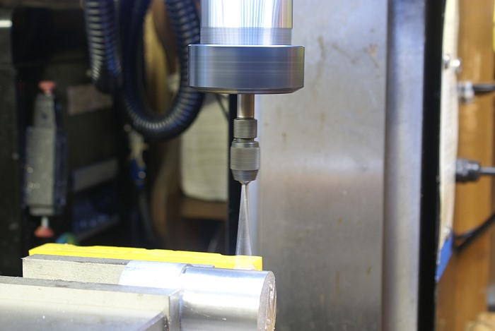
The Wiggler is a tool that fits in your mill or drill chuck. It usually comes with several different interchangeable stems which are held in the Wiggler mandrel by light friction. It does two things well. It helps you find the exact edge of a work piece and it can help you find the exact center as well. Both being pretty handy information to have. Here is a photo of mine with the .250 inch ball end stem installed.

wiggle1.jpg


Finding An Edge:

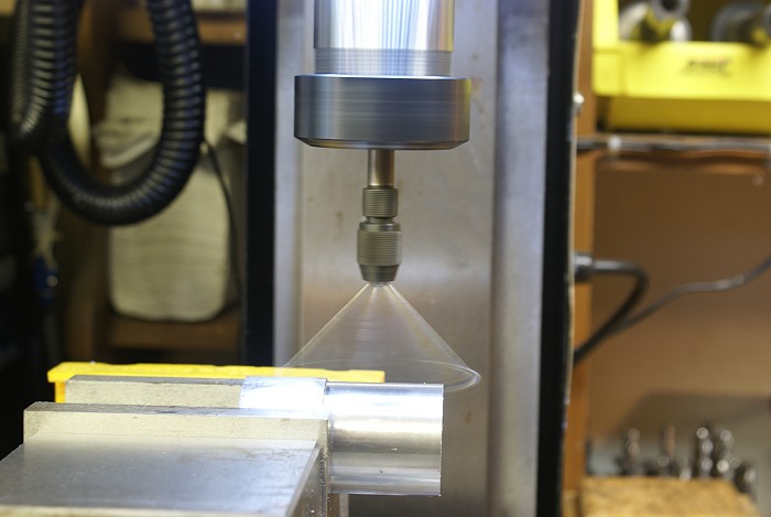
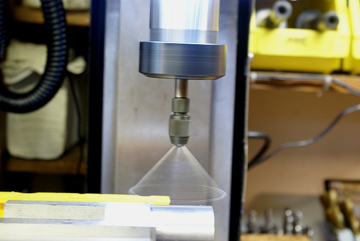
To find an edge the Wiggler has to .... well.... wiggle. The stem is first set off center just enough to cause it to rotate around its own axis as shown below.

wiggle2.jpg


It is then advanced slowly into the edge of the work piece until it stops wiggling. As it stops wiggling you'll want to slow the advance to a near stop.

wiggle1.jpg


All of a sudden the stem will "snap" and will slide off to one side or it will begin to rate in a wide circle. This is what you want it to do. I usually do this procedure twice, just to eliminate any error. You can shut off the machine at this point. .

wiggle3.jpg


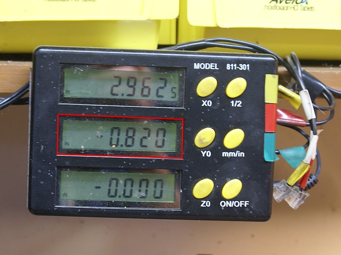
You are now .125 inches from the exact edge of the work piece. (remember the ball end on this stem is .250 inch... half the diameter equals .125 inch) By moving the table in the Y axis into the work piece .125 inches and setting the zero on your dial or DRO, you are now on the exact edge of the work piece. Repeat this procedure on the X axis to establish the X=0.000 datum point ,as well.

wiggle4.jpg


Installment #2 will come later this evening so stay tuned.

Steve
 
Hello Steve: May I be so uneducated as to ask the following question? Would it not be better for the "wiggler" to be "centered on it's own axis" as you state before approaching the workpiece? If you do this the ball will not beat against the workpiece and possibly damage itself over time. It will still touch and swing as it makes contact the same as you show. Am I missing something? I often use mine with the pin "centered on it's own axis" to line up on scribed lines and center the pin, does this differ somehow?
No argument intended, just trying to find out if I am using the tool incorrectly or this way is better for a reason. I realize that on the cylindrical edge finders that this is the way they work.
Thanks for your taking time to show "How too" posts.
don
 
Steve,
I like wigglers. They are easier for me to see than the cylindrical edge finders in more common use today. But, I us the cylindrical edge finder more often as it is about 2 inches shorter and approximates the normal length of tools I use on a regular basis. It just saves me from having to crank the table down and then back up to accommodate the longer wiggler. That gets harder every year.

The extra length does help if you are trying to reference to a location that is somewhat buried below a surface feature on a part.

Another place I use a wiggler is to pick up the edge of a narrow slot on a part, say 1/8 or 3/16 wide. I have a point that is .100 diameter that is flat bottomed so I can pick up on a 1/8 wide slot that is less than a 1/32 deep.

What RPM do you normally run your wiggler at? A study was made many years ago, by Starrett or B&S I think, on the best RPM to use a cylindrical edge finder for the best accuracy for edge finding, and concluded that about 800 RPM was optimum for most materials. I run both my wiggler and cylindrical edge finder in that general range. Generally I use from 600 to 1000 RPM. What is your feeling on this?

Gail in NM,USA
 
DParker
There are a number of ways, I'm sure, that are perfectly correct when using the tool, but by setting the stem "off axis" you get a great visual cue as to when the "snap" is about to happen. As you approach the work piece the wiggle gets smaller and smaller until it disappears. That is when you creep up on the dials so you stop at the moment of the snap. It's just how those old timers designed the darned thing. Wear isn't much of a factor since the resistance of the mandrel holder can be adjusted to have minimal effect.

Gail...
I usually run mine somewhere between 500 and 800, but I wasn't aware there is a "best speed...LOL. I too use the smaller .100 and .050 stems but the .250 just seems to wind up in the holder when I grab it. Hang with me here... I'll be sharing a couple of more techniques, as I go along....LOL. I've seen the Rattler style as well as the new Electronic and Laser types. I've just never used them so I can't really write about them.

Steve

 
Okay... family duties complete, tummy full and we're off and running again. The first series of photos showed how to find the edge of the work piece. If you went on to repeat the process on the X axis you've managed to locate yourself on the exact corner of the work piece where X = 0.000 and Y = 0.000. From there you can locate any given point on a work piece with known dimensions, including the center point..

Locating the Center Point:
Lets say you've just put a piece of metal in the vise and we have no idea of its actual dimensions. We still need to locate the center point for the operation we need to do. No problem, Sparky.

You'll want to go through the same procedure used in the first installment, above. This time, when the snap comes, we'll ignore the .125 inch the ball end contributed to the previous equation and set the zero without subtracting anything. We now want to move to the rear of the work piece. Since you already zeroed the front edge, keep tabs on the distance traveled while at the rear of the work piece. When the snap comes, make note of the distance traveled on the dial or DRO.

The Wiggle....

wiggle5.jpg


The wiggle disappears....

wiggle6.jpg


And the SNAP.....

wiggle8.jpg


Distance traveled is 1.487 inches. This time we can ignore the .125 inch because we cancelled its effect out once we moved to the rear. It effectively cancels itself out when we measured it from dual directions.

wiggle9.jpg


Divide the distance traveled by half to determine where to move the table's Y axis. In this case we want to move it to .7435 inches, which is the center line of the work piece.

wiggle10.jpg


Set the Dial or DRO to 0.000

wiggle11.jpg


Again... repeat these steps on the X axis and you will be positioned dead center of the work piece. In this scenario, the X =0.000 and Y =0.000 is located a the exact center of the work piece instead of the at the corner where we located them in the first example.

Steve

Still More to Come.....


Great tutorial Steve!

I loaned my "work" wiggler to a young man who was there on a training
co-op from a local tech school.
I have no idea just how fast he was spinning it, or what happened, but the]
next time I used it I discovered the shank of the .250 probe was bent.

The company replaced the defective probe, and I never allowed loaned that
kid another tool. When I'm on the clock every minute counts.
Trying to figure out why I'm not getting repetitive answers from a wiggler
just doesn't fit into the day.

Sh!T HAPPENS!
But when it happens without being told about it the rules change.

I'm looking forward to your continuing tutorial.

Rick
 
Steve has so masterfully handled his balls so I will get down to the pointy thing
The wiggler has a VERY sharp part. The way I do it is to chuck up the wiggler with the pointy item installed. Then turn on the mill so that it is rotating at a reasonable speed. The pointer is not concerentic with the spindle and is drawing a small circle> I (being brave and dumb ) use my thumb nail to gently coax it into concentric. OSHA probably would want you to use a 6" steel rule. Now you have the point in line with the spindle. If you have a center pip that you are trying to align then put the point down in the hole (with mill turning ) and with draw it above the work. If the center is drawing a small circle then you are not aligned with the hole and further adjustments to X & Y are nesserary. When you can drop it into the hole and pull it out without it moving then you are aligned with the pip.
 
If the gods of chance played havoc with me when working with nice flat, squared surfaces, they were positively filled with mirth when I would try and find the center of round stock. I bought a tool with a V shape and a centering mark that was supposed to get me dead on center, but it often left me in the lurch with a hole placement that was close but no cigar.

The darned thing probably worked ok, but my old eyes just never seemed sure that the two indicating marks were perfectly aligned. To add to the problem, I was also prone to second guessing the tool when other real world visual references just didn't look right.

This next trick is credited to the guy who showed it to me, not too long ago. Tim (Zeusrekning) demonstrated it while I was visiting him in his shop and I'll be eternally grateful to him for doing so. I even stopped him and made him do it twice so I knew I had it solidly in my head. God Bless you Tim....LOL

To center round stock as shown below, the Z axis comes into play in a crucial manner. It makes sure your Wiggler always hits the mark at the same elevation, so that all things remain equal. To begin, position the Wiggler's stem at a point above the center line of the round stock. Any elevation will do but lower seems to work better than higher. I use the ball end, while Tim uses a conical stem. Either one will work fine.

wiggle12.jpg


Now set your Z axis to Zero on the dial or DRO. This isn't crucial but setting it to zero makes it easy to see if anything moves from the original setting. This level is where you'll want to do the rest of the process.

wiggle13.jpg


Form here, the process is exactly like wiggling the square stock we centered earlier.

Wiggle the front side....until the wiggle goes away...
wiggle14.jpg
.

and the Snap happens...
wiggle15.jpg


then Zero the Dial or DRO
wiggle16a.jpg


Again... we have to wiggle the rear of the work piece and measure the distance traveled.
wiggle16.jpg

wiggle17.jpg

wiggle18.jpg


The distance traveled is 1.640 inches which we divide by half (.820 inches) .
wiggle19.jpg


We move back toward center to the .820 point, which is the exact center line of the work piece.
wiggle20.jpg


Once again , by measuring the work piece from opposing directions, the .125 compensation for half the .250 ball can be ignored completely, due to physical cancellation. Set your Y dial or DRO to zero and you're ready to drill a centered hole.

Steve

More tomorrow... it's getting late/early here.
 
A short comment on Steve's demo of finding the center of the round bar in the vise in the Y direction:

An alternative is to indicate on the inner jaws of the vise rather than the piece itself.

By coincidence, my shop instructor just last night showed us another way to find the center, when more precision is needed than an edge finder can give. Using a clamp on the spindle of the mill to attach a dial indicator, you swing the DI around to each jaw measuring its deflection against the vise jaws. Adjust the saddle dial and repeat until the indicator shows the same reading on both sides. You're in the center! This procedure should be done as close as possible to the workpiece to eliminate any variation in the jaws caused by clamping pressure. The wiggler method is a lot quicker than this method, so use only when extra accuracy is needed.
 
Locating the proposed hole:
The previous installment could probably use an addendum. To accurately position the placement of the hole we were drilling when i went to bed, we would wiggle the end of the work piece to establish an edge, as we did in installment #1. From there it's only a matter of moving to position to drill the hole right where you want it.

Steve
 
As Steve has pointed out you can use either DRO or dial. When using your dial, all reading should be taken from the same direction CW or CCW.Say our mark is .040 on the dial we turn .025, .030,.035 .042, oops went over .002. You can not just turn back to .040 because of back lash. Turn back about .050 and try again. It is hard for me to write this as I use a DRO and my dials have about .060 or .070 back lash. I don'tt worry about backlash because the DRO measures actual table movement
 
...or for a quick, reasonably accurate method of finding the center of round stock: install a small endmill in the spindle, adjust the Z until the tip of the cutter barely touches the stock, fire up the spindle motor and traverse the Y which leaves a very small, flat cut in the center of the stock. Put your pointy wiggler or a small fixed point in the chuck and carefully center it on the flat. You'd be surprised how accurate this is, especially if you use one of those magnifier headband gizmos and a good light.
 
Kvom anticipated my next installment quite nicely.

The one centering job that had me buffaloed for quite a while was centering vertically positioned round stock that hadn't been in the lathe prior to being placed on the mill. I could pretty much cheat to the center by using the little pip point the lathe always leaves on a faced surface, but fresh metal has no such landmarks. Since I was never sure I was wiggling at the very apex of the curve, I was also never sure I was going to find the exact center.

It finally dawned on me that I had a pair of pretty dependable flat surfaces readily available within the Vise jaws. This technique assumes you've swept the vise with a DTI and everything is nice and square. The Vise I use flexes very very little when it's tightened down, so I'm able to depend on these surfaces for establishing usable datum points. Your mileage may vary, depending on the vise and its "character flaws".

As Gail noted earlier, this same technique can also be used to establish the center of existing slot cuts. You just use the walls of the slot as we'll be using the jaws of the vise. After all an open gap between two walls is pretty much a slot, by definition.

I've explained the steps for wiggling several times in this series, so this time, due to the number of photos, the explanations and commentary will be somewhat brief. By now you've seen the wiggle and snap routine several times, even if you haven't given it a try.

Once the round stock is in the vise and secured, we'll want to place the wiggler inside the gap between the Jaws and wiggle the front jaw, first.

wiggle21.jpg


wiggle22.jpg


wiggle23.jpg


After the snap, be sure to zero the Y dial or DRO, as before.
wiggle24.jpg


Now move the wiggler to the rear jaw and wiggle it, as well.
wiggle25.jpg


wiggle26.jpg


wiggle27.jpg


Distance traveled = 1.506 inches
wiggle28.jpg


Divided by half and the centerline is located at .7503 inches.
wiggle29.jpg


Once the table has been advanced to the centerline, there is no problem finding the apex of the curve. Simply move the wiggler up to clear the vise, wiggle the side of the round work piece and set the zero when the snap happens.
wiggle30.jpg


wiggle31.jpg


wiggle32.jpg


wiggle33.jpg


The next step is to wiggle the other side of the X axis of the work piece, noting the distance traveled.

wiggle34.jpg


wiggle35.jpg


wiggle36.jpg


Distance traveled = 1.906
wiggle37.jpg


Move the X axis back by half the distance traveled, to .953 and you are centered on the round stock
wiggle38.jpg


Zero the dials or DROs and you're ready to go.
wiggle39.jpg


An operation that once bedeviled, now wears a halo....(grin)
wiggle40.jpg


This concludes my contribution to the thread, but I'm going to ask that those of you who suggested alternate techniques and tricks take the time and add to this thread. It's the little things like this that make the new guy's life a bit more bearable. I had to stumble about on the net tolearn most of the things i've shared. Lets make it easier on the next guy....eh?

Steve
 
If, for some reason, you can't access the vise jaws when center finding cylindrical stock, you might want to keep the Osborne maneuver in mind. For those unfamiliar with it, I've done a writeup to accompany the program I wrote to examine the convergence of this procedure.

Note that this procedure works nicely if the stock is not centered in the vise jaws, as may be the case with (circular) features on a casting.

============================================


In his book, "Home Machinist's Bedside Reader #2 (pg. 159)", Guy
Lautard describes the "Osborne Maneuver" for accurately centering round stock
in the milling machine using nothing more than an edge finder.

It works like this. Accurately measure the diameter of the stock.
For description purposes, let's assume that the y axis is along the 12-6
o'clock line of the stock and the x axis is along the 3-9 o'clock line. Align
the edge finder by eye to the 3 o'clock position and locate the edge of the
workpiece. Now move by half the diameter towards the center of the stock along
the x axis. Now, use the y axis controls to find the edge of the stock near
the 12 o'clock position. Move half the diameter towards the center of the
stock along the y axis.

Now do it again. Use the x axis controls to find the edge of the
stock near the 3 o'clock position. Move half the diameter towards the center
of the stock along the x axis. Use the y axis controls to find the edge of the
stock near the 12 o'clock position. Move half the diameter towards the center
of the stock along the y axis.

As you repeat this procedure again and again you will approach the
center of the stock with ever increasing accuracy. (In mathematical terms,
the procedure converges to the center of the stock.)

The question becomes, "How often do I have to do this?". The answer
is, "Probably fewer times than you think!". I wrote OSBORNE.EXE to examine
how fast the process converges. For example:

OSBORNE MANEUVER

Workpiece diameter [2] ?
Initial offset [0.1] ?

iteration: del1,del2,error= 1: 0.10000000, 0.00501256, 0.10012555
iteration: del1,del2,error= 2: 0.00501256, 0.00001256, 0.00501258
iteration: del1,del2,error= 3: 0.00001256, 0.00000000, 0.00001256
iteration: del1,del2,error= 4: 0.00000000, 0.00000000, 0.00000000
iteration: del1,del2,error= 5: 0.00000000, 0.00000000, 0.00000000
iteration: del1,del2,error= 6: 0.00000000, 0.00000000, 0.00000000

Here we have a 2 (we'll say inch but units don't matter) diameter
workpiece and we initially aligned with an error of 0.1". That is to say, we
initially aligned by eye to the x axis at the 3 o'clock position with an error
of 0.1". If your eyes are that bad, you need better glasses! After the first
iteration we're still 0.1" off the x axis (del1), but we're within 0.005"
(del2) of being on the y axis. Our radial error (distance from the center of
the workpiece) is the root-sum-squared of del1 and del2 or 0.100126". On the
second iteration, del1 becomes the del2 of the previous iteration and that
puts us within 0.0000126 on the x axis. The iterations continue in this
fashion with del1 always becoming the del2 of the previous iteration.

As you can see, even with a hideous initial error we've converged to a
nearly unmeasurable error after only three iterations. You can use the
program to experiment with other combinations of workpiece diameter and
initial error. Personally, I do it twice and don't worry about it.
 
You gotta love the point where the wiggler just goes ballistic! It makes me smile. Edgefinders do it too, but the wiggler has more exuberance!

FWIW, while this weighty discourse of whirling whizbangs is available, let me add that Tormach has a wonderful video showing the use of a conventional edgefinder as well as the electronic kind:

http://www.tormach.com/mfg_database.htm

Near the bottom of that page. Worth a watch to really get the idea.

I've got a wiggler for the lathe, but didn't buy one for the mill. I've got a set of Starrett mechanical edge finders, as well as a new Fowler LED model (on sale somewhere for $24). I just got the Fowler and really like it. Anyone here know why you spin an electronic edge finder? The mechanical versions need to spin to show their answer, but the LED lights up and doesn't. Yet you still ought to use one spinning as it shows in the video. (I know the answer, but thought it'd be a worthwhile riddle to throw out).

Here's one I don't know the answer to at the moment, though I have some speculative ideas on where I'd start. What's the best and quickest way to test the accuracy and repeatability of several edge finding techniques?

Cheers,

BW
 
Steve..... :bow:

Having just been given the starret type of finder and being told how to use it and having an hour on it the other day... I find this thread very interesting.

I will now have the knowledge to see why I was going to just off centre ...(well half the dia off!) doing my calc's a bit wrong!

Thank you, these are the kind of things some of us never seemed to do correctly from the book description!


Ralph.

 
Ralph,
Don't feel too bad, I still manage to forget which stem I'm using and subtract the wrong measure...LOL. I'm glad the tutorial was of help to someone. The idea for the thread came to me after Tim showed me his centering tricks.

Sometimes it's the little things we get used to doing, all the time, that we forget to share with others coming along after us. Hopefully more of these types of tips will be forthcoming from the old farts who are hanging out in the corners....(grin)

Bob...
Okay...I'll bite. Why do you need to spin an electronic edge finder. (feeling as if I just asked how many M.E.'s does it take to change a light bulb)

Steve
 
Cedge said:
Bob...
Okay...I'll bite. Why do you need to spin an electronic edge finder. (feeling as if I just asked how many M.E.'s does it take to change a light bulb)

Steve

So that any runout in the spindle is included in the measurement, the edgefinder has to spin just like a cutter would.

Cheers,

BW
 
El Stevo cheap and cheerful edge finder.

Everyone has one of these but they don't know it.

Sort around in the bits box and find a ball race, preferably a sealed bearing, with a decent OD, like 1" or 20mm, some nice whole number, now find a bit of drill rod, silver steel etc that fits the inner race, cut a bit off about 2" to 2-1/2" long and press in the bearing with a dab of Loctite.

That's it job done, one edge finder.

To use:-
Hold the top of the shank in the chuck and run at about 500 to 800, not critical and bring the edge of the bearing up to the edge of the work.

Just as it contacts the work it slows to about 1/2 speed, you are now 1/2" or 10mm away from the work depending on what size bearing you selected.

If you do go mad and have a crash, so what, just press a new bit of bar in and away you go again.
Also works on the inside of a bore for finding the centre etc.

.
 

Latest posts

Back
Top