Gears, gears and more gears

Home Model Engine Machinist Forum

Help Support Home Model Engine Machinist Forum:

This site may earn a commission from merchant affiliate links, including eBay, Amazon, and others.

John S

Well-Known Member
Joined
Apr 13, 2008
Messages
654
Reaction score
41
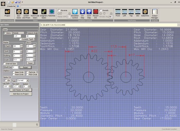
Been working with Art Fenerty of Mach3 fame on his new gear-cutting program.
Basically brought about because he wanted to do clock gears and then it got all out of hand with eccentric gears and all that artistic crap.

Link to the site at www.gearotic.com there is a demo copy but the tutorials are worth watching.

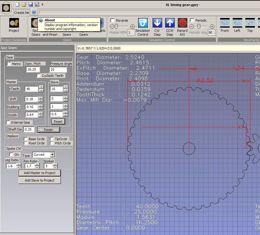
Anyway I wanted to get the program back to making mechanically perfect gears and bring in some ideas. Most of the cutting is for routers making thin gears with a vertical spindle but there is an option for doing spur and helicals travelling across the face.

Now for the good bit even though CNC is needed the gears are cut with a conventional off the shelf $3 end mill and that end mill will cut any gear provided it can reach the root, don't believe it, watch the video.......

[ame=http://www.youtube.com/watch?v=qZJ95I3ZWro]http://www.youtube.com/watch?v=qZJ95I3ZWro[/ame]

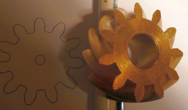
Not a great picture, the white nylon doesn't help but I'll redo it later on brass or similar. Main thing is it shows the operation, the cutter blocks a slot out and then by using all 4 axis at the same time it moves away, raises the cutter and rotates the 4th axis so each pass is at a different angle and part of the involute. You have the choice of selecting how many passes per tooth.

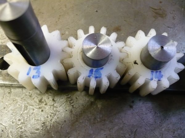
But because specials cutters are not needed it's now very easy to modify gears to fit an application. I cut two 14 tooth gears to text book specs, mounted then on two pins the required distance apart and they ran perfectly, I then made two more identical blanks but cut 13 on one and 15 on the other.

gear_cluster2.jpg


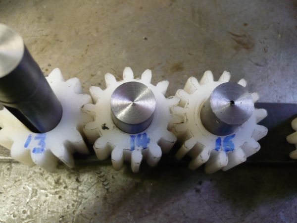
You can swap these in any order and they run fine. Helicals are still a work in progress, they work but the tooth shape is not correct yet.

helical_2.jpg


Again simple tooling, in most of these cases the tool was a throw away FC3 3mm end mill costing £2.99

John S.
 
Excellent. How small can you go, assuming one is willing to work with small cutters? Is Mod 1.0 possible? Is G-code generic enough to run on something other than Mach?
 
You will need a 1mm cutter for 1 MOD.

1modscreen.jpg


Sample screen with a 20 and 15 selected.

G Code is very generic, you may have to edit a couple of start up lines but the main code should run on most machines.

John S.
 
Is there any chance that they will take on bevel gears with a tapered milling cutter?
I have a 20o per side cutter ready for the experment but I have not found the time yet.

Dan
 
Yes later, it's on the cards but again no special cutters will be needed.
For a bevel you will need the 4th axis tilted from flat to the required pitch angle and t will roll it to 'plane' the involute.

Some of the work has already been done.
 
Very interesting, John. Can you use a single diameter cutter for different gear pitches, assuming it is small enough to reach the bottom of the dedendum?

Chuck
 
Yes Chuck, everything I have done so far has been done with a 3mm end mill £2.99 off the shelf, except the gear 13 tooth corrected gear in the pic below and that needed a 2mm cutter to get into the root.

gear_cluster3.jpg


What I did here was to cut two standard 14 teeth gears and put them on pins at the correct centre distance to check them and they ran OK.

Then I made two more blanks exactly the same size and corrected the teeth to get 13 on one and 15 on the other. No matter where you place them they run correctly.

Because this all runs in software you can plat " What If ? " to your hearts content.
Not quite what you want to fit in? How about a 18.5DP cutter or better still to get bang on a 18.67564 DP ?

Sooooooo.

I drew a 40 tooth XL series timing pulley up in CAD [ with the help of Mr SPI Industries ] and got some measurements off it.

They went back to Gearotic [TM] and juggled some figures.

XL%20timing%20pulley%20gearotic.jpg


So if we use 16.25 DP we get an OD of 2.5240, we need 2.5240, OK so far

Then play with shift, stubbing and tooth width we get a total depth of 0.0571, we need 0.0550, 2 thou too deep, think I can live with this.

Tooth width is 0.1242 and we need 0.1240, even closer.

Now bung the dxf onto the original drawing and it's within a gnats left bollock.

Only fly in the ointment is it says it wants a-0079 thou cutter but I reckon it can get away with a 40 thou cutter. I think this is all to do with going off standards on the shift and stubbing etc and I have asked Art to check this.

It's still early days on this program but so was Mach3 at one stage and look where it is now.

Once saved all that is needed to make any XL pulley is to change the number of teeth.

John S.
 
I have been using a great little program called "involute" by Graham Baxter. I have cut gears down to mod 1.5 in plastic with a 1.5mm end mill cutter. The involute form is very good and I cut several gears which meshed together very well. The program does not need a 4th axis, it just uses the x and y to move the cutter for the involute form and z to cut down into the stock material. I cut the gear in several passes to alleviate damage to the small cutter, so the gears take much longer to cut than they would with a 4th axis - as seen from the video above. I have not used the new version of involute available from http://www.delphusa.com/ but hope to get it soon.

Cutting at mod 1 with a 1mm cutter would be interesting - I am not sure whether this would be possible in brass ? I suspect the cutter would probably bend too much and also loose its cutting edge.

I have no affiliation with the company - just found the software easy to use and it worked great.

The program also helped me to design a flywheel - just used the spokes part of the program and omitted the gear making section. It worked well, and fly wheels with different spoke numbers (4,5,6,7,etc...), rim thickness, spoke taper and hub diameter are easy and quick to program - probably much quicker than with a CAD program. Involute generates the g-code directly as well as produce a DXf file of the gear.
 
Involute is a good program for spur gears but the cookie cutter aproach of cutting the outline of the gear will not work with bevel or any type of sprial gear.

This program uses a generating type of cutting which needs a 4th axis. This is what is needed for straight or curved face bevels so I am very happy to be able to make proper bevel gears for my Shay projects.

Dan
 
John S,
Some of us play with small toys and the end mills will get impractical for large DP/small mod gears.
Using the Gearotic program is there any reason that a slitting saw could not be used instead of an end mill by transposing the Y and Z coordinates? Of course an extended mandrel would have to be used to clear the indexer due to the relatively large diameter saw and spiral gears would not be possible.
Gail in NM
 
Can't see any reason why not but it will have to be a side cutting saw because it 'planes' the involute at each pass using the side.

Interesting idea though.

John S
 
Cool stuff, especially the helicals.

Would a single-point threadmill (side-v-cutter type) or so work from the side? Those aren't real cheap, but it's not far from there back to an easier-to-grind flycutter... Might not work so well for helical and complex shapes though.

 
Back
Top