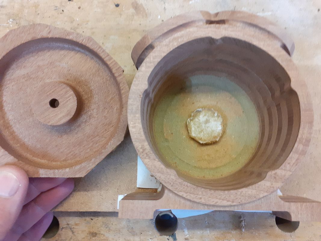
What is the thinking with that hopper top pattern?
I would have thought you would make the pattern with a core print at the top and no detail of the hole. The radiused corner on the underside would be formed by the core so no need to produce it on the pattern.
View attachment 135072
I am not sure I completely thought it through.
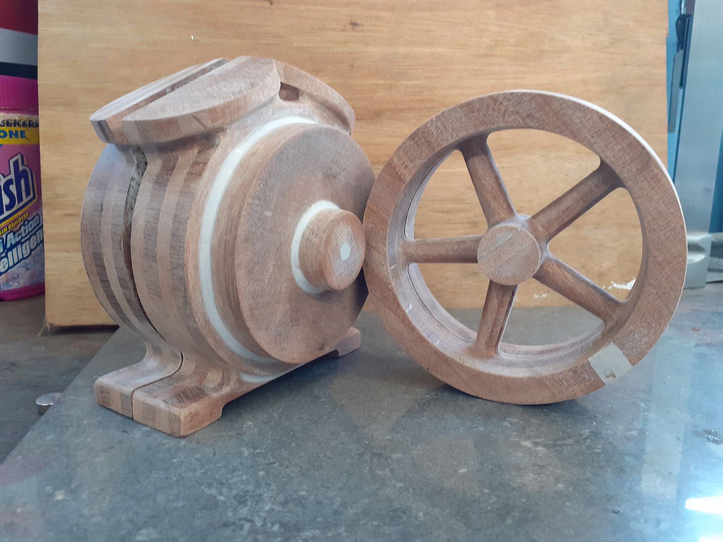
Sometimes I just print the various parts first to get a feel for the size of things/assemblies, potential parting lines and gate postions, etc.
And I was still toying around with cores, and how to make them in SW.
One school of thought is to make a split pattern, such as for the Galloway water hopper, fill it with bound sand, and let it set.
Then drill a down in the top and glue on a round core print.
I considered 3D printing patterns with core prints on them, but am trying to avoid that, and just print the patterns as-is, and add core prints on the fly.
I can adhere various core pieces with ceramic adhesive, and so it is not critical that the cores all be in one piece.
Just thinking out loud, perhaps another train of thought would be to ram the water hopper pattern with bound sand, and use a large wood dowel rod in the center. Then make a round bound core using a piece of PVC pipe slit on one side, and slide the round core into the hole, to make core prints.
If and when I can get back out into the shop, I will no doubt play around with several methods.
I am straining to recall my methology, but as I remember, the intent was to eliminate the need to make a pattern with core prints protruding out, and then also have to make a corebox for the core.
My intent was to just 3D print the part (in this case the water hopper) exactly as it is, with shrinkage allowance to make the pattern slightly larger, and not have to make both a pattern and a corebox.
Smarter, not harder, as they say.
I generally find that if everyone else does it a certain way, then there most certainly is a much better way to do it, given modern bound sand, 3D printing, etc.
This was a challenge in mental recall for me.
I am no spring chicken anymore.
Edit:
Probably not a very good example, but on the green twin, I made the base pattern, and then just made the cope and drag molds.
No cores required, although for the first mold I attempted for that part, I did make a core, and tried to anchor it in unbound sand.
Bound sand is the only way to fly in my opinion, and it solves so many problems.
If you really must have a corebox, make a negative of the part in SW, and then 3D print the corebox.
But generally, just use the part itself as a corebox and save a ton of time and effort.
Edit02:
Someone mentioned that I did not need to cut a hole in the plywood for this pattern, but rather just place the flat side down, ram one side, flip it, and ram the other side.
I learn as I go.
The odd flask shape is to save on sand, which is not easily reused.