Gail's version of Chuck's Horizontal single is alive

Home Model Engine Machinist Forum

Help Support Home Model Engine Machinist Forum:

This site may earn a commission from merchant affiliate links, including eBay, Amazon, and others.

GailInNM

Administrator
Staff member
Administrator
Global Moderator
Joined
Feb 17, 2008
Messages
2,326
Reaction score
440
And still another version of Chuck's Horizontal single is running. It still needs a base and some tinkering with the springs. It will probably be a little while before I get around to that.

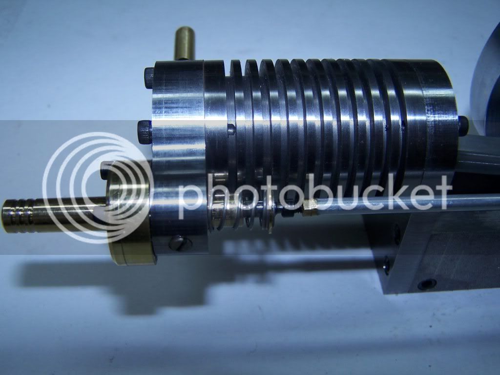
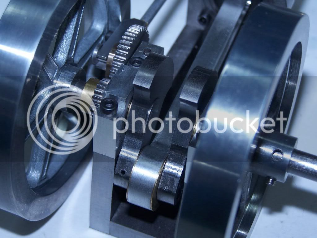
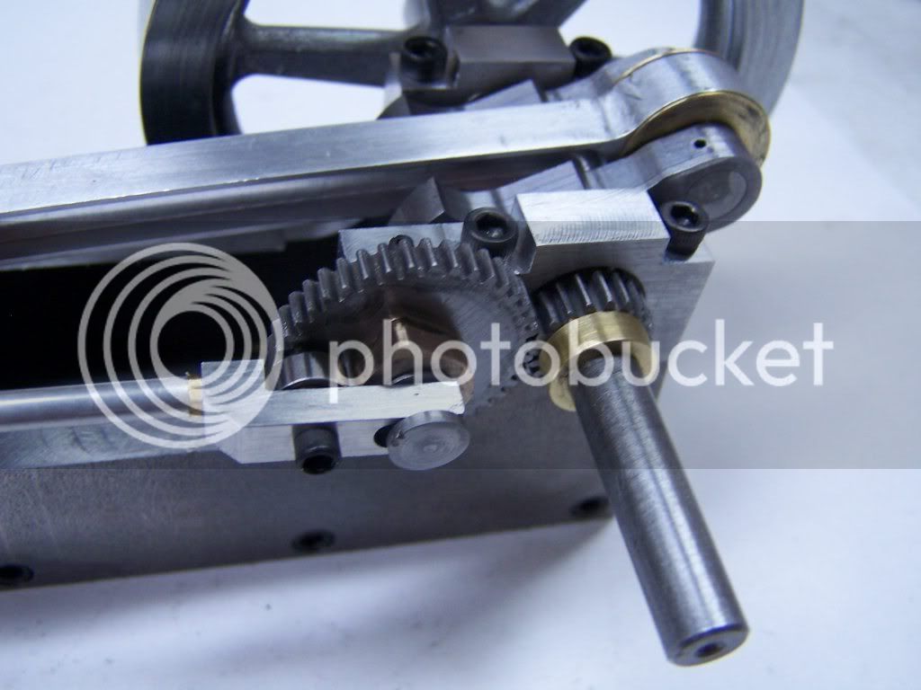
The cylinder and piston are cast iron. The flywheels came out of my old castings box and are zinc. I think that I only had one casting session with that pattern and the pattern is dated 1984. But they were about the right size and weight. The base is built up of 1/4 CRS plate pieces screwed together. The crankshaft is built up with the rod in place during construction. The rod has a 1/4 X 1/2 ball bearing in the big end. I put fins on the cylinder, well just because I like fins. Not what you would want for steam, but it will probably never see steam. Looks right for an IC engine which it supposed to sound like. And on air, they won't make any difference.

Video is first run. RPM is about 180. 20 PSI with a needle valve in the line to regulate speed. Sorry about all the background noise.
Gail in NM, USA

[ame]http://www.youtube.com/user/nmsteam#p/u/7/Aj9aco2viLM[/ame]
 
Nice one Gail ;D

I like fin's... Not the people...I don't know any of those! ...I like the ones you made ;D I think they add quite a nice look to the engine, which is looking very good.

I don't remember seeing any build photo's in the WIP section? Were there any? if not could you post a still photo or two please? Just so I can take a closer look at those flywheels and some of the other detailing ;D


Ralph.


Very nicely done Gail and the video shows it off well !! This design would make a nice addition to any steam/air collection with its unique sound and valve arrangement. Beautiful finish to the engine as well.

Bill
 
Gail,

Very Nice ! :bow: :bow: :bow: I like the fins too, Hmm, maybe I need to chuck the cylinder back up in the lathe??? ::)

-Bret
 
Great Job, Gail. You're engine looks a heck of lot better than mine :-[.

I'm still experimenting with air feed, piston valve springs and sizes to get a sharper exhaust note.

I've tried using a pressure regulator to vary the speed. It makes for a very smooth run and slow idle speeds, but the exhaust note is lacking.

Higher pressures and restriction of the air volume seems to give a better sound. Keeping the cam dwell short also improves the sound.

Chuck
 
Thanks for the comments/advice/suggestions everyone.

For those just joining us, here are some of the links to earlier work on this style engine.

Photos and description of Chuck Fellows Engine that started all this madness
http://www.homemodelenginemachinist.com/index.php?topic=2088

Chucks drawings for the original
http://www.homemodelenginemachinist.com/index.php?topic=2100.0

Bret's work in process
http://www.homemodelenginemachinist.com/index.php?topic=2154.0

Bret's video of his first runs
http://www.home.earthlink.net/~lhartswick/Diamond-turning-facing/3Final-version.jpg


Today I hope to get som drawings done up for the first round of changes that I know that I need to make on this engine.

Ralph, I did not do a WIP on this engine, so there are no previous photos. When I get the new parts made, I will do a complete tear down on this engine to both install the new parts, but to also clean up some of the existing parts. I will take some detailed photos of the parts while it is in little bitty pieces as well as some of the partially assembled engine so you can see the relationship.

Chuck, thank you for starting this all and for the helpful information that you have been passing along all the way.

Bret, thanks to you also. We were building at almost the same time. You were a good boy and posted progress all the while. I am a hermit, so did not post anything. Your WIP was most helpful.

There is nothing like successful prototypes to follow to make life easier.

Gail in NM,USA
 
I really love these Horizontal Single's 8) ............. very nice work Gail and a big thanks to Chuck, Bret, yourself and BS ;D for all the input. I'm determined to have a go at one a little further down (or should that be "up") the "learning curve", for the moment though I think it probably best to set my sights a little further down the scale, just where though still remains a mystery ???

CC
 
Here are some photos of the first run configuration. I plan to tear it down soon for retrofitting with new parts I am making now so the next photos will be different.
Fellows1.jpg


Fellows2.jpg


Fellows3.jpg


Fellows4.jpg
 
Gail, how did you fasten the cam to the cam gear?

Chuck
 
Chuck,
I made the cam and the gear hub as one piece out of SAE 660 bronze. The gear is just a 1/8 thick gear blank cut from 12L14 steel. Actually I cut the gear as a 2 inch long section so I could make up new gear/cam assemblies and switch them out as a unit so I could try different cams easily. The hole in the gear blank is a finger press fit on the hub part so a drop of Loctite 680 makes them as one. The hub is reamed to 0.203 and the shaft is turned to fit. Then I turned down the end to 3/16 to fit the bearing cap mount and allow free play. When I turned the shaft down, I turned the 3/16 part 0.005 eccentric to the 0.203 part so I could rotate the shaft and set the gear backlash if necessary. Always a good idea with homebrew gears and all that sort of thing.
Gail
 
Wow! Two of these great engines at the same time. Wonderfully done in both cases. Similar, but each uniquely differant. Now I earn to build one!
 
Gail, I really like the cam idea too. I was thinking of a cam that style, having worked on the cars for years.... That's what a cam looks like in your head!

I am Eagerly awaiting what you are retrofitting.... surely there can't be much you could change.... it looks and runs so well! ;D

I may leave it for a while... so that I have a lot of knowledge built up first.... then I might tackle one of these very cool engines ;D


Thanks for the photo's,


Ralph.
 
:eek: :eek: :eek: Very Nice work Gail..I'm thinking at my next work... :big:

Paolo
 
Gail,

Very impressive cam/gear setup. Certainly more adjustable than my beveled nub in the setscrew hole of a purchased gear. I must give gearcutting a try ;)

-Bret
 
Thanks for the comments everyone.

Bret: Gear cutting is quite easy once you get started. I have a full set of 48 DP and 64 DP cutters that I have acquired mostly one or two at a time as I needed them over the years. The gears for this engine are 48 DP with 20 and 40 teeth. The number of teeth selected was so I could cut them with a 5C speedy indexer which only goes in one degree increments. I have an dividing head so I can cut any number of teeth, but it is too heavy for an old man to lift safely on to the mill table by myself, so I have to wait for someone to come over to help me to both mount it and then put it away.

The gears were cut from 12L14 and I cut an extra long section for the cam gear so I could make up extra cam/gear assemblies as needed for playing. It took about an hour to prep the stock and cut the gear stock so I can just slice off as needed. See attached photo.

First order of business on the changes is to make up a new cam. The cam diameter has to increase to get the dwell time I want, so this means making up a new shorter push rod. The push rod is a length of 1/8 OD x0.014 wall hobby shop aluminum tubing with a 2-56 threaded bushing Loctited in each end with Loctite 680. The bushing are turned from 1/8 AF brass hex stock to make adjustment easier.

Fellows5.jpg
 
Speaking of gears, as cutting them is certainly out of my league at present I was browsing for UK suppliers ??? ........... without much success I might add, the only ones I found that might work were These, bit they seem a bit too thick (or .... wide).

Does anyone have a link to a UK supplier for suitable items.

Cheers ;)

CC
 
GailInNM said:
Video is first run. RPM is about 180. 20 PSI with a needle valve in the line to regulate speed. Sorry about all the background noise.
Gail in NM, USA

Gail,

What kind of needle valve did you use for speed control? Is it something you made? Got a picture or a rough drawing?

Thx...
Chuck
 
Back
Top