Expansion Link Help

Home Model Engine Machinist Forum

Help Support Home Model Engine Machinist Forum:

This site may earn a commission from merchant affiliate links, including eBay, Amazon, and others.

Runner

Well-Known Member
Joined
Feb 10, 2011
Messages
124
Reaction score
17
Hi all,

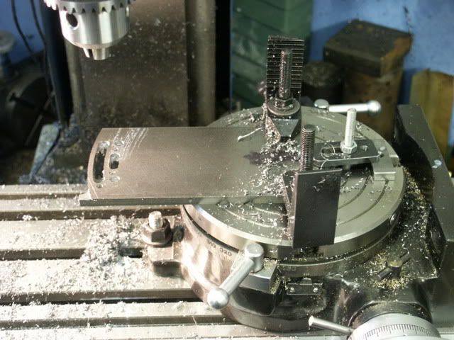
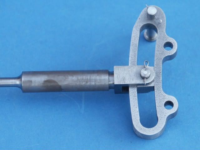
I am making expansion links for a steam locomotive. I need to produce a curved slot at 4 7/8ths " radius 3/16ths" width and a 1/16th" deep. I have a lathe only no milling machine. A simple method is to mount the piece on a faceplate at the required distance from the lathe axis and use a parting tool mounted on the cross slide facing the faceplate to produce the slot. However, this method requires at least a 10" faceplate and a lathe capable of swinging it, which I don't have. 9" is my limit. LBSC's words and music (ref The Mechanical Engineer Sept 9th 1948 ) refers to a simple set up that can be used with smaller lathes to produce the slots but is silent on how this can be done:confused:.

Can anyone enlighten me?

Thanks in advance.

PS Any help is welcomed, it doesn't have to be iaw LBSC's version.

Brian
 
Last edited:
Do you have a vertical slide? L.C. Mason described a way to do it on the lathe using the slide, a pivot and a milling cutter in the spindle. If you have the slide then I'll dig out the details.

J
 
Hi Jason,

thanks for the response. No I don't have a vertical slide, but maybe I can jury rig the compound slide on an right angled bracket clamped to the cross slide. It rather depends on how rigid I can make it. I have avoided milling in the lathe but I suppose I must grab the nettle.

Please let me have the details of LC Mason's method.

Brian
 
Last edited:
Without proper machinery, mill, faceplate, rotary table, the next best thing is making it by hand. Take a piece of stock the required thickness and blue it up. Lay out the inside radius of the link. Cut it as close as possible and then file to the line. Now start again on another piece of metal and cut the outside radius. When you have the two pieces finished make 2 small blocks for the end caps and silver solder them in place. Another alternative would be to lay out the needed arc, drill side by side holes and then file to the finished size. When I got started I didn't have all the tools needed to do some jobs so making by hand was the only option. I'm sure with a project like this you will be making many other parts by hand.
gbritnell
 
Brian,
I can think of at least one way to cobble up something to do this job but by the time you've found the materials and built the setup, if it could be built on your lathe at all, you would have expended quite a bit of time, so much so that all things considered I would have to agree with gbritnell, this is a job to do by hand. Using the time that would've been required to make the radius cutting setup you can do just as good a job.

If the links are only 1/16" thick, I would make them in a solid piece, and I would rivet the blanks together and do them both at one go. I would begin by opening the slot up throughout its length by pre-drilling and then by whatever best means at your disposal I would file the inside (smaller) radius to as nearly it's final radius AND to as nearly a true arc as you can. Then I would open the slot up with further filing until I could pass a 3/16" diam rod (silver steel preferably) at one extreme end. I would then proceed to file along the slot by try & fit, taking off just enough metal from the outside radius to allow the rod to move along the slot, keeping in mind that the difference in the rod moving along, and not moving along, will probably be only one file stroke. With careful work you will end up with slots that are a gnat's whisker over 3/16" and to as true an arc as you initially made the inside edge.

I think another opportunity this job presents is to discover what you can accomplish by hand and from that gain personal satisfaction and an increased confidence in your own ability.
 
Last edited:
Back to the method you originally described, there is no need to have a 10" faceplate as the work can overhang the edge. Also you don't need to be able to swing 10" as you are only moving the work in a small arc by hand so no risk of hitting the lathe bed. You may need to mount the tool on the outsid eedge of the tool post to get it far enough from the lathe axis. Much like this one is overhanging my rotary table.

expansion.jpg


This is Masons set up. A pivot hole is drilled in the plate and a suitable pivot pin attached to an angle plate at centre height. The other end of the bar is drilled for another pin which is free to slide in a tee slor of the vertical slide.

When the slide is wound up and down the bar moves in an acc and if the pivot is set 4 7/8" behind the lathe spindle you will get your radius slot.

link.jpg
 
Thanks Jason, L C Mason's setup requires a flat cross slide to stand off the angle block providing the pivot point. Southbend lathes unfortunately does not have that feature.

Thanks gbritnell and Harry for your hand made methods. I am struggling to fully understand what's being described but at my age that's not surprising. I'll try harder.

I have attached a sketch which shows the expansion link.

Brian

Expansion Link.jpg
 
George and Harry's method was assuming that its a flat link like this one below

PICT0110.jpg


I still think it can be done on the end of a piece of flat bar overhanging the faceplate like you describe but move the bar by hand so it does not need to swing a full circle
 
The overhang method appears OK in principle. However, the diffilculty of moving the faceplate by hand proved to require more muscle than I could muster. A 3/16" parting tool was too great a drag and after an hour I had achieved about a 0.015" cut. After which I was ready for a sit down. I have to think of another way.

Brian

IMG_4208.jpg
 
Drill out some of the waste then use a narrower tool to do each side of the curve at a time.

Also if you have a longer bar to mount the work on that will give you more leverage

J
 
I think that you should be looking for an auxiliary spindle on the saddle.

THIS is what Curly Lawrence described as his method( In Maisie) Again, Sparey describes his variation in the Amateur Lathe whilst a score of writers before and since have waxed lyrical about 'overhead gear'

In a bygone, forgotten era, I 'up rated' ( joking) the idea by suggesting that a common or garden electric hand drill using a (then) 43 mm collar was what I used and I went on to prattle about a Bosch POF 45 wood router as a tool post router. It wasn't quite rocket science and as far as I know it all was really a damp squib.
 
There are a few ways to skin a cat, however I have decided to go with the hand made recommendations, using filing and silver soldering. This I have termed a sandwich construction. The attached sketch is my solution.

Brian

IMG.jpg
 
Brian,
I have two suggestions relative to your sketches. First, I would file and finish the inside radii of the center plates while they are still within a larger piece of metal. That is, I wouldn't profile the outside edges first. If you shape the outside first, if your sketch is proportionately accurate, there won't be enough metal around the inside slots to hold their shape accurately while you file the insides. (If you realized this already, sorry for belaboring the point.) Secondly, the heat of silver soldering could distort these rather delicate assemblies. Since they aren't exposed to fire or boiler heat (I assume) my inclination would be to simply soft solder them together. This would provide more than enough strength.
 
Last edited:
Thanks Harry,

I have already made the centres and did as your recommendation to produce the inside profile before profiling the outside edges. Being only a 1/16th" between the inside and outside profiles as you said wouldn't allow sufficient metal to allow the outside to be done first. I actually soft soldered 4 plates (2 expansion links) together to provide greater strength during the filing and ensure that they are all the same profile.

The locomotive utilises Walchaerts valve gear and requires the radius rod to pass through the expansion link. The die-blocks have to be inserted through the holes in the pieces that I have termed 'backs' and the pin that enables the radius rod to connect to the die blocks has to be inserted through these holes. The pin has to be a force fit so getting the two die-blocks and the radius rod to line up so the pin can be pushed home appears to be a fiddly job. So I have decided against silver soldering the spacers to the outside/centres instead using 2 X 9BA screws on each spacer. This method will enable me to assemble the radius rod to the die-blocks and then assemble the expansion link around the radius rod.

Using screws negates the need for the backs/centres to be silver soldered at all. Getting solder inside the centres is something I want to avoid. But soft solder can easily be scraped off if it affects the operation of the die-blocks in the expansion link. So soft solder it is!

Brian
 

Latest posts

Back
Top