Electronic Ignition, no doubt its been done before.

Home Model Engine Machinist Forum

Help Support Home Model Engine Machinist Forum:

This site may earn a commission from merchant affiliate links, including eBay, Amazon, and others.

jpeter

Well-Known Member
Joined
Aug 6, 2010
Messages
464
Reaction score
39
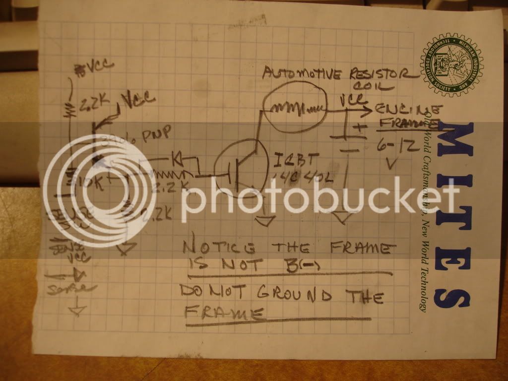
I've been fooling around with electronic ignitions for a while. Being basically a cheap kind of guy I thought maybe I could build one cheaper than buy one. Not only that but I like fooling around with electronic stuff, especially the kind that can shock me. well I made one. After it worked my buddy needed one too so I made another. Some of you might also need one so here I published the plans; schematic.
DSC02180.jpg

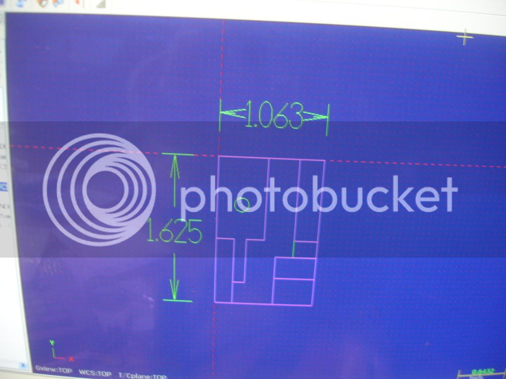
The next picture shows the cutting pattern for the circuit board. I milled each line 1/16 wide. The first one I built I ground the traces with a Dremel grinder. Milling made for a much nicer job. Why is one line green, I don't know.
DSC02174.jpg

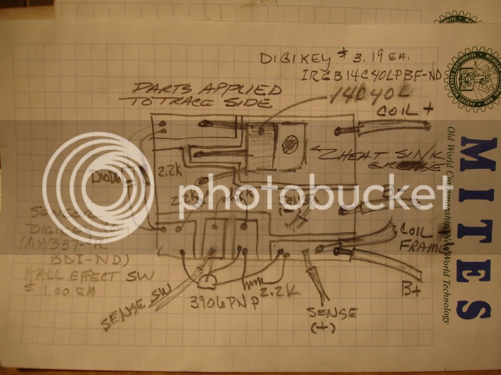
The next picture shows the parts layout. I included some infor about where to get the parts and current prices. Be sure to get a few hall effect sensors cuz they've been know to get zapped by the high tension. Keep all high tension wires and stuff away from the battery and the rest of the electronics or you'll zap a sensor. You'll need a south pole magnet attached to your camshaft or crank shaft to fire the sensor. Interesting too is that you can series multiple sensor outputs so, for example, on a hit'n miss you could arrange a sensor to block firing the plug when coasting; extend battery life. (I actually have never done that. I know you can parallel them. Maybe I ought to think about that a little more.)
DSC02179.jpg


Here's a picture of the final product.
DSC02172.jpg

As you can see, neatness is not a requirement but in my defense I had to do a little development and modification on this version. Try it, you might like it.
 
Hi Jim
Im hoping I can do something with this great idea :)
But I may have to leave the link open for an hour or so till the pics open
I seem to have a few computer gremlins running around here at the moment
Thanks for the design (I think LOL)
Pete
 
I built this for a new single cylinder engine a buddy has just completed. The last ignition I built was for my v8 and it's worked well. I had a lot of zener diodes though attached to the sensor cuz it was in the distributor close to the high tension wires and had kept burning out the sensor. After adding the spike protection it worked well. Anyway, this one is set up so the sensor is remote to any spark wires so I didn't worry about the sensor getting zapped. I should have. In service the sensor didn't last at all. After the sensor burned out for the third time he removed it and added cam actuated contacts, points but not big like current carring points, to fire it and its working very well in that mode. I guess I need to do more development.
 
If you want to make them live, then the zener diodes are very important. Clamp all the inputs and outputs, and remember even the coil primary will have ~400v back emf when the col fires and it helps to clamp that to ground as well. Zeners are cheap, the job they do is priceless.
Another thing you want to watch out for, is old oil filled coils are usually fine with full current flowing all the time, but modern E-core or epoxy filled coils will burn up quickly at anywhere near a full duty cycle. You have to make certain that the engine never stops with the hall sensor conducting, running your transistor into a 100% duty cycle.
 
Nice clean lil schematic Jpeter! :) I love the ability to make metal and electronics work in harmony!

chi-town

ps. much love to the UP :)
 
Hey Lakc, I've been having good luck using automotive coils with built in resistors. Is their anything special to watch for If I stick with that style?
 
I am not sure I have ever seen one with a built in resistor, but my experiance is mostly Chrysler, I cant say they dont exist. Ballast resistors and resistance wires were mostly for Kettering points style ignition. Chrysler stayed with the ballast resistor when they went to electronic ignition and the oil filled round coils. When GM went to the HEI system and the first E-core coil they had circuitry to prevent "overdwelling" and dropped the resistance wire.

Modern coil on plug systems dont use any type of resistor, the coil is dwelled only long enough to reach max flux then fired immiedately, essentially timed in reverse by the microcontroller. In the interim there were other ways to prevent too much coil current from coils with no real heat sink ability.
 
Lakc, autoparts stores have them. They look just like the traditional coil but they'll have "internal ballast resistor" printed on the case. They cost about $20 at the usual suspects. When cars had points they all had a ballast resistor, some used a resistor wire and some had a ceramic resistor. And I agree, coil on with no resistor means major load on the output fet and coil too.
 
Ok, aftermarket, that makes sense. Nothing different along those lines, the FET is somewhat protected by the resistor if it is stuck on for a length of time. Given enough heat sink it should be fine. Overall, just avoiding leaving the ignition turned on when the motor isnt running should be enough protection.
 

Latest posts

Back
Top