Easy-to-make Fly Cutter

Home Model Engine Machinist Forum

Help Support Home Model Engine Machinist Forum:

This site may earn a commission from merchant affiliate links, including eBay, Amazon, and others.

Ken Bartlett

Well-Known Member
Joined
Dec 1, 2009
Messages
48
Reaction score
5
I have just recently(as of 2 days ago), brought home my first milling machine, a used Harbor Freight X2. After stripping it down, cleaning, reassembly and setup was done I am ready to start on my first engine. Listing in my head the required tooling I will need to complete the project, I realize that a fly cutter would help in bringing some of the stock down to size and produce a nice surface finish. Are there any suggestion on a easy to make fly cutter that a novice can make. I do have a Harbor Freight 7 x 10 mini lathe as well for the turning work required. Drawings for said fly cutter would be great, as well as recomendations for spindle speed for cutting aluminum with the fly cutter as well. Any and all comments are welcome. Thanks.

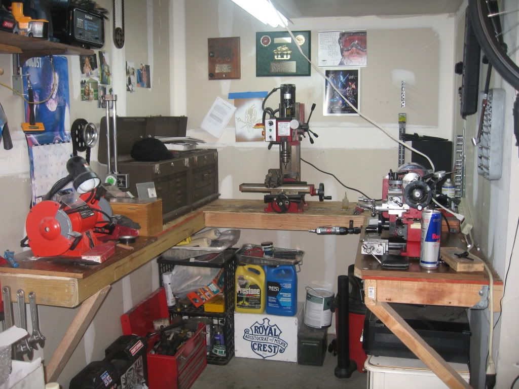
My very small corner of our 2 car garage.
http://i208.photobucket.com/albums/bb66/THEBARTLETT/MyShop/12-3-09001.jpg[/img]]
 
Thank you sir for the quick response! Going over the drawing for the tool, it looks very straight forward enough. I think I have just the right size material in the scrap box. With a little luck it should go quick. Ill post pics of the process I take to make it as well as the completed tool. Thank you again.
 
Bah...my dad is Sir, I'm just webby. :big: Glad I could help! ;D
 
Oh my goodness. So that is the secret to Blogs flycutter!

Thanks websterz!!
 
I forgot to mention, be careful running a flycutter on an x2 mill, or any mill with plastic gears for that matter. There are few things that can shell out a gear faster than jamming the spindle with an over aggressive flycut. If you are going to pursue machining as a serious hobby we need to get you set up with a belt drive conversion. No sense laying out the case for one, here are the plans I used to build mine:

http://www.hossmachine.info/projects_6.html#belt conversion
 
Thanks again!! I actually ordered yesterday the intermediate gear and the motor gear from LittleMachineShop.com, since I found the motor gear chiped and looking like its ready to go. Also the previuos owner had replaced the intermediate gear with a badly fabricated aluminum one. Needless to say the top cover plate was full of aluminum shavings when I stripped it yesterday for cleaning. Ill look over the plans from the link you posted and see if its something I can wrap my head around. And sorry about the "sir" reference, its a force of habit. I am a former Marine, old habits die hard.
 
What's the story with the butterfly wrench bolted to the bench?

As for sizing parts, I use the flycutter only for surface finish taking .002" or so cuts. For removing more material I use endmills. But tyat's just me, and I have a BP. In any case, a roughing endmill is excellent if you need to take off significant amounts.
 
Ken,
I'd like to reinforce what websterz and kvom said.

For removing lots of material use a roughing end mill.

The fly cutter is only for making shallow cuts over a large area. The idea is to make a nice finish and a flat surface, not removing a large amount of material. This is especially true on smaller machines like the X2.

Also, make sure your tram is good. Because of the large "disk" of the fly cutter an out of tram condition will be exaggerated. You could easily end up with a step on your finished surface.
 
Thank you all for the advice. I definitly will think ahead more on the application of my tools and cutters to work within the limitations of the machine. I will use my endmills to bring the material to size and finish with the flycutter. I am actually heading out to the shop to start making the flycutter now. Will post up some pics as I progress with it. And I have my tram set within a thou or so in x and y, so I believe Im good their.
As far as the pneumatic wrench mounted to my bench, it is a quick and dirty setup to mix paint of all things!! I attach a metal paint mixing paddle I bought from The Home Depot, mount it to the wrench via a keyless chuck attachment, hook up the air and let it rip. The wrench's speed is low enough that I don't get paint flying every where. And since I am able to keep the paint bucket on the ground with this setup, I simply put a clamp on the actuator and stand back. Very handy lately, since during winter my wife has me painting everything in site. Thanks all for the help so far, and will report back on my progress.
 
A modification to the flycutter plans is to offset the shank by 3/16" or even 1/4" so that the cutter tip is on the small side. By doing this, you get a kind of counterbalance flywheel effect and it (is supposed to) reduce some of the stresses in surfacing.

Dave
The Emerald Isle
 
So that I understand you correctly Dave, the centerline of the spindle would be located on the centerline of the cutter, or at least to that side of the main body. Have I got that right? It all sounds very reasonable, I have a need to machine up a flycutter and think this would be a good 'adjustment' to make.

BC1
Jim
 
To use the cutter, I always start at the right side of the work and feed the work to the right. I set the table so that the tip of the tool is just outside the front edge of the work when it's closest to me. This setup has two advantages:

1) Most of the chips get thrown towards the back of the table rather than at me.

2) The tool tip contacts the work at a very slight angle, making for less vibration. Assuming a good tram, the trailing side of the cut removes very little material.

 
BC1

Move the axis of rotation from the centre of the body towards the cutting tip by the required amount (distance will depend on the diameter of the body). Easy in the 4 jaw chuck. This will put the counterweight directly opposite the cutting tip. Does that make sense to you. Unfortunately I am not at home for a couple of weeks so cannot show a picture of mine.

Dave
The Emerald Isle
 
OK, I get it now, thanks. I wonder why it is that the commercial units aren't set up that way. It would sure seem to reduce the amount of shaking from the imbalance while performing a cut.

BC1
Jim
 
While I haven't been machining all that long, I haven't yet found a need for a fly cutter. I have the same mill and lathe. It doesn't take me long to polish up most pieces I've milled with a buffing wheel, especially after running the piece over some sandpaper first.

 
Well, I started on the cutter this morning, but very quickly realized I did not have the correct size material in my scrap box. The only piece I had was about 1 1/2" too short. So I decided to change the plan a bit. I will use the larger piece of material I have to make the "head" portion. Then I will make the shank from a piece of 3/4 4140CF. I will drill/tap and bore a hole for a light press fit in the head, press in the shaft, then setup in the lathe to turn concentric afterwards. Milling the 10deg angle slot and drill/tap setscrew holes after that. I am fairly confident it will work. Below is a quick picture of starting to rough the "head" to size.

http://i208.photobucket.com/albums/bb66/THEBARTLETT/MyShop/120609061.jpg[/img]]

I ended up being to greedy with my cut, tried to take a heavy .050 and ended up popping my only fuse. Had to head to TheHomeDepot to get a few extra. I started on the upright and base of my engine when I got back for a change of pace. Below is the pic of what I have completed so far. Only need to finish the cylinder and piston now.

http://i208.photobucket.com/albums/bb66/THEBARTLETT/MyShop/120609066.jpg[/img]]

Per the drawings the hole in the cylinder is to be bored off center. I do not have a 4jaw chuck for my lathe, so intend to drill and bore it on my mill. Anyone see a potential issue with that strategy? Will update further on the fly cutter as it progresses.
 
I was able to get a piece of round stock, 4140HR from work the correct size today. I got it turned to size very nicely, got it setup in the mill and took off material for the 10deg angle on the bottom face. I then proceeded to completely screw the part up. I don't know what the hell I was thinking. After indicating the center of the part, I moved the table in the y axis to make the slot for the tool bit, which of course is off center. Well somehow my dumb ass went the wrong way!! I got the slot milled to depth and width, was admiring my craftsmanship, when I then noticed the error. The cutting surface of the toolbit, which is suppose to be on center of the flycutter, is now on the wrong side. It of course would work if I could run the machine in reverse, which I cant since my mill is an X2 and doesnt go in reverse. Well crap, will start all over again tomorrow. Very hard learned lesson tonight, need to pay attention to the details and get it right the first time.

http://i208.photobucket.com/albums/bb66/THEBARTLETT/MyShop/FlyCutterFailure003.jpg[/img]]
 

Latest posts

Back
Top